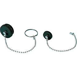
NJW Waterproof Cap
Cliquez sur cette image pour l'agrandir.
Cliquez sur cette image pour l'agrandir.
- Remise sur volume

● Prevents intrusion of dust and foreign matter to the fitting part when connectors are not connected.
● It prevents accidents caused by touching live parts when not connected.
● 3 models are available: for straight, for relay, and for panel mounting.

·Other series connectors cannot be used.
Référence pièce
Vous pouvez trouver ici le numéro
de référence lié au produit recherché.
Spécifications
| Model | Shell Size | Type | Weight (g) |
| NJW | 16 | PCA For Straight | 18 |
| 20 | 20 | ||
| 24 | 22 | ||
| 28 | 13 | ||
| 16 | RCA For Panel Mounting | 10 | |
| 20 | 11 | ||
| 24 | 13 | ||
| 28 | 9 | ||
| 16 | ADCA For Relay | 11 | |
| 20 | 13 | ||
| 24 | 14 | ||
| 28 | 11 |
Plus d'informations
Référence pièce
|
|---|
| NJW-16-ADCA |
| NJW-16-PCA |
| NJW-16-RCA |
| NJW-20-ADCA |
| NJW-20-PCA |
| NJW-20-RCA |
| NJW-24-ADCA |
| NJW-24-PCA |
| NJW-24-RCA |
| NJW-28-ADCA |
| NJW-28-PCA |
| NJW-28-RCA |
| Référence pièce |
Prix unitaire standard
| Quantité minimale de commande | Remise sur volume | Specifications | Compatible Shell Size | |
|---|---|---|---|---|---|---|
7.81 € | 1 | Disponible | 5 jours | For Relay | 16 | |
12.05 € | 1 | Disponible | 5 jours | For Straight | 16 | |
5.31 € | 1 | Disponible | 6 jours | For Panel Mounting | 16 | |
7.74 € | 1 | Disponible | 6 jours | For Relay | 20 | |
13.28 € | 1 | Disponible | 5 jours | For Straight | 20 | |
7.09 € | 1 | Disponible | 5 jours | For Panel Mounting | 20 | |
10.37 € | 1 | Disponible | 5 jours | For Relay | 24 | |
18.08 € | 1 | Disponible | 5 jours | For Straight | 24 | |
9.66 € | 1 | Disponible | 5 jours | For Panel Mounting | 24 | |
13.92 € | 1 | 5 jours | For Relay | 28 | ||
23.65 € | 1 | Disponible | 5 jours | For Straight | 28 | |
13.03 € | 1 | Disponible | 5 jours | For Panel Mounting | 28 |
Loading...
Waterproof Medium Type Connectors (NJW)
Features
● NJW series connectors are round metal connectors, designed to enhance water-proofing functionality when mated. (IPX7 equivalent)● Light weight and superior strength enhanced by zinc die cast material (aluminum die cast for the shell size 28 connectors).
● Some of the products in the NJW series are PSE certified under the Electrical Appliance and Material Safety Law, and therefore can be used safely as a power supply.
● There are 3 types of connectors: Straight, relay, and panel mount connectors.
● Because these connectors are connected by soldering, no dedicated tool is required for wiring.
Common Specifications
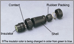
Materials / Finish
| Item | Materials | Finish |
|---|---|---|
| Shell / Dustproof Cap | Zinc or Aluminum Alloy (shell size 28) |
Chrome Plated or special chemical processing |
| Insulator | Synthetic Resin | - |
| Contact | Copper Alloy | Silver Plating |
| Rubber Packing | Synthetic Rubber | - |
Characteristics
| Item | Contents |
|---|---|
| Rated Current | Check with the table below. |
| Rated Voltage | Check with the table below. |
| Withstand Voltage | No abnormality such as short circuiting occurs when regulated voltage is applied for 1 minute between immediately adjacent conductors. |
| Insulation Resistance | 1,000 MΩ or higher when measured between immediately adjacent conductors with regulated voltage. |
| Contact Resistance | Conductor resistance is 5 mΩ or less when a pair of contacts are connected at up to the regulation length. |
| Vibration Resistance | No functional defect was found during the JIS C 5025 vibration test. Contact resistance is 5 mΩ or less. |
| Impact Resistance | No functional defect was found during the JIS C 5026 shock test. Contact resistance is 5 mΩ or less. |
| Repeated Operation | No functional defect was found when a removal and insertion sequence was tested 500 times. Contact resistance is 5 mΩ or less. |
| Humidity Resistance | No functional defect was found during the JIS C 5023 humidity test. Insulation resistance is 100 MΩ. |
| Temperature Cycle | No functional defect was found during the JIS C 5030 temperature cycle test. |
| Corrosion Resistance | No functional defect was found during the JIS C 5028 salt water spray test. Contact resistance is 5 mΩ or less. |
| Waterproofing | No abnormality such as flooding was found when left under water pressure of 0.4 kgf/cm2 at regular working conditions for 24 hours or more. |
| Operating Temperature Range | -25°C ~ +85°C |
Table of Basic Specifications
| Product No. | Shell Size |
Number of Cores | Shape Symbol | Rated Current (A or less) |
Rated Voltage (V or less) |
Withstand Voltage AC (V) |
Insulation Resistance (MΩ or higher) |
Contact Resistance (mΩ or less) |
Compatible Wire Size | Applicable Electric Wire Finished Outer Diameter (mm) Note 1 |
|
|---|---|---|---|---|---|---|---|---|---|---|---|
| AWG | Conductor Section Area mm2 | ||||||||||
| NJW | 16 | 3 | PF, RM, ADM |
10 | 125 | 1,500 | 2,000 | 3 | 16 | 1.25 | 8.0 ~ 11.0 |
| 5 | 5 | 1,000 | 1,000 | 5 | 20 | 0.5 | |||||
| 16 | 3 | PM, RF, ADF |
10 | 125 | 1,500 | 2,000 | 3 | 16 | 1.25 | 8.0 ~ 11.0 | |
| 5 | 5 | 1,000 | 1,000 | 5 | 20 | 0.5 | |||||
| 20 | 2, 3 | PF, RM, ADM |
15 | 250 | 1,500 | 2,000 | 3 | 14 | 2 | 7.0 ~ 12.5 | |
| 4, 5 | 10 | 16 | 1.25 | ||||||||
| 7 | 1,000 | ||||||||||
| 12 | 5 | 1,000 | 5 | 20 | 0.5 | ||||||
| 20 | 2, 3 | PM, RF, ADF |
15 | 250 | 1,500 | 2,000 | 3 | 14 | 2 | 7.0 ~ 12.5 | |
| 4, 5 | 10 | 16 | 1.25 | ||||||||
| 7 | 1,000 | ||||||||||
| 12 | 5 | 1,000 | 5 | 20 | 0.5 | ||||||
| 24 | 2, 3 | PF, RM, ADM |
20 | 250 | 1,500 | 5,000 | 3 | 12 | 3.5 | 9.5 ~ 15.0 | |
| 4, 5 | 15 | 14 | 2 | ||||||||
| 10 | 10 | 1,000 | 2,000 | 16 | 1.25 | ||||||
| 14, 16 | 5 | 1,000 | 5 | 20 | 0.5 | ||||||
| 24 | 2, 3 | PM, RF, ADF |
20 | 250 | 1,500 | 5,000 | 3 | 12 | 3.5 | 9.5 ~ 15.0 | |
| 4, 5 | 15 | 14 | 2 | ||||||||
| 10 | 10 | 1,000 | 2,000 | 16 | 1.25 | ||||||
| 14, 16 | 5 | 1,000 | 5 | 20 | 0.5 | ||||||
| 28 | 16 | PF, RM, ADM |
10 | 250 | 1,000 | 2,000 | 3 | 16 | 1.25 | 12.5 ~ 18.0 | |
| 24 | 5 | 1,000 | 5 | 20 | 0.5 | ||||||
| 28 | 16 | PM, RF, ADF |
10 | 250 | 1,000 | 2,000 | 3 | 16 | 1.25 | 12.5 ~ 18.0 | |
| 24 | 5 | 1,000 | 5 | 20 | 0.5 | ||||||
Note 1: Even connectors with the same shell sizes may be divided into 2 or 3 types depending on the thickness of the cable used. Take care at selection. Refer to each product page for further details.
Contact Arrangement Diagram
Connection Work Method
Configurer
Propriétés de base
-
Specifications
- For Panel Mounting
- For Relay
- For Straight
-
Compatible Shell Size
-
Filtrer par type de données CAO
Filtrer par jours d'expédition standard
-
- Tous les articles
- 5 jours ou moins
- 6 jours ou moins
Propriétés optionnelles
- Les spécifications et les dimensions de certaines pièces peuvent ne pas être intégralement indiquées. Pour plus de détails, reportez-vous aux catalogues des fabricants .
Assistance technique
Mode de paiement


Fabrication à la demande
Certificats


Copyright © MISUMI Corporation All Rights Reserved.