Confirmé
- Specifications
- Compatible Shell Size
- 16
- Jours d'expédition estimés
- Tout
- Dans les 5 jours ouvrables
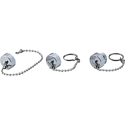
NWPC Waterproof Cap (NWPC-16-PCA)
Spécifications du produit
Spécifications

| Model | Shell Size | Shape Symbol | Weight (g) |
| NWPC | 14 | PCA For Straight | 31 |
| 16 | 34 | ||
| 25 | 43 | ||
| 30 | 80 | ||
| 40 | 118 | ||
| 44 | 144 | ||
| 50 | 207 | ||
| 54 | 273 | ||
| 60 | 307 | ||
| 64 | 345 | ||
| 14 | RCA For Panel Mounting | 14 | |
| 40 | 15 | ||
| 44 | 27 | ||
| 16 | RCA For both panel mounting and relay | 34 | |
| 25 | 59 | ||
| 30 | 86 | ||
| 50 | 97 | ||
| 54 | 133 | ||
| 60 | 117 | ||
| 64 | 156 | ||
| 14 | ADCA For Relay | 13 | |
| 40 | 60 | ||
| 44 | 87 |
Plus d'informations

Plus d'informations
Informations de base
A waterproof cap for preventing foreign body contamination and protecting the connected portion.

● Prevents intrusion of dust and foreign matter to the fitting surface when connectors are not connected.
● IPx6.

· The 3 models of caps are for straight plugs, relay adapters, and panel mount receptacles.
Spécifications communes
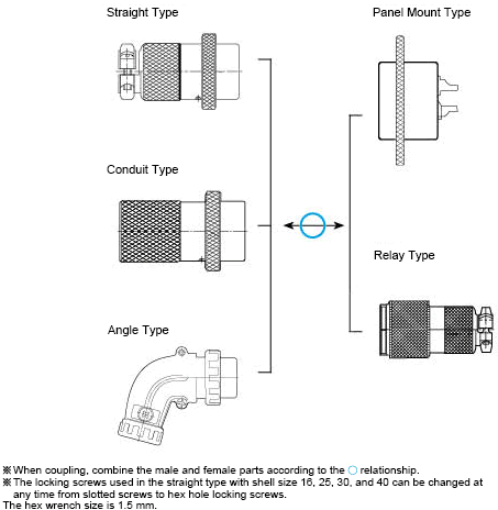
General-purpose Large Metal Connector (NCS)
Features
● NCS series connectors are round metal connectors that have been used conventionally as general-purpose type connectors.● The structure is simple, robust, mechanically and electrically stable; some items have acquired the mark (Electrical Appliance and Material Safety Act compliant), so they can be used widely from power supply to signal transmission.
● There are 10 shell sizes, each of which offers a selection among panel mounting, cable mounting, and relay mounting, providing a wide variety of combinations to suit the application.
● Because these connectors are all connected by soldering, no dedicated tool is required for wiring.
● The structure is an original design and cannot be coupled with other companies' products.
Common Specifications
Material / Finish
| Item | Materials | Finish |
|---|---|---|
| Shell / Dustproof Cap | Zinc Alloy or Brass | Chrome Plated or special chemical processing |
| Insulator | Epoxy Resin | ー |
| Contact | Copper Alloy | Nickel-plated (Shell Size 14 ~ 30) |
| Silver-plated (Shell Size 40 ~ 60) | ||
| Gold-plated (Shell Size 30, 13-core) |
Combination Method
Characteristics
| Item | Characteristics |
|---|---|
| Rated Voltage, Current | Check with the table below. |
| Limit Operating Voltage | Check with the table below. Shows the limit voltage value for continuous use of the NCS connector. |
| Withstand Voltage | No abnormality such as short circuiting occurs when regulated voltage (see table below) is applied for 1 minute between immediately adjacent conductors. |
| Insulation Resistance | Check with the table below. Resistance value when measured between immediately adjacent conductors with specified voltage. |
| Contact Resistance | Check with the table below. Conductor resistance value when a pair of contacts are connected at up to the regulation length |
| Humidity Resistance | No functional defect was found during the JIS-C-8306 humidity test, and the insulation resistance is 10 mΩ or higher. |
| Heat Resistance Test | No functional defect was found during the JIS-C-8306 heat resistance test. |
| Temperature Rise | Under correct operating conditions, the temperature rise in conducting parts is 40°C or less when rated current is flowing. |
| Corrosion Resistance | No functional defect was found during the JIS C 5028 salt water spray test. |
| Allowable Operating Temperature Range | -40°C ~ +120°C |
| Shell Size |
Number of Cores | Shape Symbol | Rated Current (A or less) |
Rated Voltage (V or less) |
Limit Operating Voltage (Note) | Withstand Voltage (VAC) | Insulation Resistance (MΩ or higher) |
Contact Resistance (mΩ or less) |
Applicable Electric Wire Size Conductor Cross-sectional Area mm2 Parentheses show AWG |
Applicable Electric Wire Finished Outer Diameter (mm) |
|---|---|---|---|---|---|---|---|---|---|---|
| 14 | 1.2 | P, R, AD | 5 | 125 | 200 | 1,000 | 2,000 | 3 | 0.75 (18) | φ5.5 ~ 7.0 |
| 16 | 1 | P, R AD |
10 | 125 | 200 | 1,000 | 2,000 | 3 | 1.25 (18) | φ6.5 ~ 8.0 |
| 2.3.4 | 5 | 0.75 (18) | ||||||||
| 16 | 2.3 | PM, RF, ADF | 5 | 125 | 200 | 1,000 | 2,000 | 3 | 0.75 (18) | φ6.5 ~ 8.0 |
| 25 | 2.3.4 | P, R, AD GP1-2, LP |
10 | 250 | 400 | 2,000 | 2,000 | 3 | 2 (14) | φ9.5 ~ 11.5 |
| 5 | 1,800 | |||||||||
| 6.7 | 300 | |||||||||
| 8 | 5 | 1.25 (16) | ||||||||
| 25 | 2.3.4 | PM, RF, ADF GPM1-2 |
10 | 250 | 400 | 2,000 | 2,000 | 3 | 2 (14) | φ9.5 ~ 11.5 |
| 5 | 1,800 | 1.25 (16) | ||||||||
| 6.7 | 5 | 300 | ||||||||
| 30 | 2 | P, R, AD GP1-2 |
15 | 250 | 400 | 2,000 | 2,000 | 3 | 3.5 (12) | φ11.0 ~ 13.0 |
| 3.4 | 2 (14) | |||||||||
| 5.6.7 | 1,800 | |||||||||
| 8 | 10 | 300 | ||||||||
| 13 | 5 | - | 1,500 | 1.25 (16) | ||||||
| 30 | 2.3.4 | PM, RF, ADF GPM1-2 |
15 | 250 | 400 | 2,000 | 2,000 | 3 | 2 (14) | φ11.0 ~ 13.0 |
| 5 | 1,800 | |||||||||
| 6 | 10 | - | ||||||||
| 8 | 5 | 300 | 1.25 (16) | |||||||
| 40 | 2.3.4 | PM, RF, ADF GP1 |
30 | 250 | 500 | 2,500 | 2,000 | 3 | 5.5 (10) | φ15.0 ~ 17.0 |
| 5.6.8 | 20 | 400 | 2,000 | |||||||
| 10 | 3-piece - 10, 7-piece - 5 | 300 | 1,800 | Contact No. 1, 9, 10-2 (14) , Others - 1.25 (16) | ||||||
| 12 | 3-piece - 10, 9-piece - 5 | Contact No. 1, 9, 10-2 (14) , Others - 1.25 (16) | ||||||||
| 16 | 3-piece - 10, 13-piece - 5 | Contact No. 1, 14, 15-2 (14) , Others - 1.25 (16) | ||||||||
| 20 | 5 | 1.25 (16) | ||||||||
| 44 | 2.3.4 | PM, RF, ADF GPM1 |
30 | 250 | 500 | 2,500 | 2,000 | 3 | 5.5 (10) | φ15.0 ~ 19.0 |
| 5.6.8 | 20 | 400 | 2,000 | |||||||
| 10 | 3-piece - 10, 7-piece - 5 | 300 | 1,800 | Contact No. 1, 9, 10-2 (14) , Others - 1.25 (16) | ||||||
| 12 | 3-piece - 10, 9-piece - 5 | Contact No. 1, 9, 10-2 (14) , Others - 1.25 (16) | ||||||||
| 16 | 3-piece - 10, 13-piece - 5 | Contact No. 1, 14, 15-2 (14) , Others - 1.25 (16) | ||||||||
| 20 | 5 | 1.25 (16) | ||||||||
| 50 | 2.3 | P, R, AD GP1 |
80 | 500 | 600 | 3,000 | 5,000 | 1 | 30 (2) | φ19.0 ~ 23.0 |
| 4 | 50 | 250 | 500 | 2,500 | 2,000 | 3 | 14 (6) | |||
| 8 | 25 | 400 | 2,000 | 3.5 (12) | ||||||
| 10 | 20 | 300 | ||||||||
| 15 | 15 | |||||||||
| 25 | 4-piece - 15, 21-piece - 5 | 1,800 | Contact No. 3, 6, 19, 22-3.5 (12), Others - 2 (14) | |||||||
| 54 | 2.3 | PM, RF, ADF GPM1 |
80 | 500 | 600 | 3,000 | 5,000 | 1 | 30 (2) | φ19.0 ~ 26.0 |
| 4 | 50 | 250 | 500 | 2,500 | 2,000 | 3 | 14 (6) | |||
| 8 | 25 | 400 | 2,000 | 3.5 (12) | ||||||
| 10 | 20 | 300 | ||||||||
| 15 | 15 | |||||||||
| 25 | 4-piece - 15, 21-piece - 5 | 1,800 | Contact No. 3, 6, 19, 22-3.5 (12), Others - 2 (14) | |||||||
| 60 | 2 | P, R, AD GP1.25 |
150 | 500 | 600 | 3,000 | 5,000 | 1 | 50 (0) | φ29.0 ~ 33.0 |
| 3 | ||||||||||
| 4 | 80 | 30 (2) | ||||||||
| 10 | 30 | 250 | 300 | 2,500 | 2,000 | 3 | 8 (8) | |||
| 15 | 15 | 3.5 (12) | ||||||||
| 30, 40 | 5 | 1,500 | 2 (14) | |||||||
| 32 | 3-piece - 15, 29-piece - 5 | Contact No. 2, 24, 28-3.5 (12), Others - 2 (14) | ||||||||
| 60 | 10 | PM, RF, ADF GPM1.25 |
30 | 250 | 300 | 2,000 | 2,000 | 3 | 8 (8) | φ29.0 ~ 33.0 |
| 15 | 15 | 3.5 (12) | ||||||||
| 30 | 5 | 1,500 | 2 (14) | |||||||
| 32 | 3-piece - 15, 29-piece - 5 | 1,800 | Contact No. 2, 24, 28-3.5 (12), Others - 2 (14) | |||||||
| 64 | 2 | PM, RF, ADF GPM1.25 |
150 | 500 | 600 | 3,000 | 5,000 | 1 | 50 (0) | φ31.0 ~ 36.0 |
| 3 | ||||||||||
| 4 | 80 | 30 (2) |
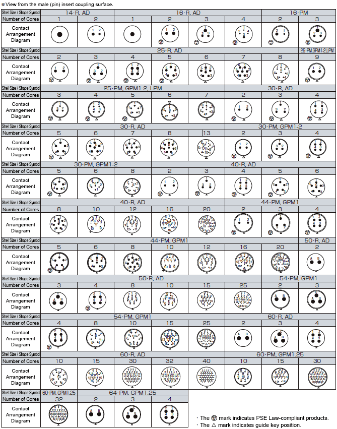
NCS Connector Contact Arrangement Diagram
Connection Work Method
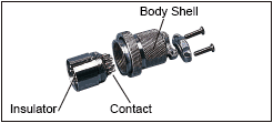
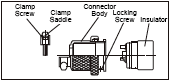
1. Disassemble the connector according to the following.
Note: If a contact for 80 A or 150 A is mounted, use the following procedure.
(1) Loosen the lock screws and remove the insulator from the connector body (turn counterclockwise)
(2) Loosen the clamp screws and remove the clamp saddle from the connector body
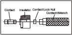
(1) Insert the contact wrench from the coupling side and remove the contact locking nut
2. Pass the disassembled parts through the cable in the order shown below.
Note: Avoid mistakes in the order or direction of parts.

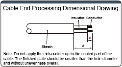
3. Following the figure and table below, perform preparatory soldering for the core wires of the end-processed cable.
4. Solder
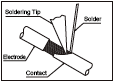 (1) Insert the core wire with extra solder into the contact solder pot
(2) Heat the contact and the core wire with a soldering iron (conductor cross-sectional area 0.75 ~ 3.5 mm2 (AWG18 ~ AWG12) 30 seconds or less, and conductor cross-sectional area 5.5 ~ 14 mm2 (AWG10 ~ AWG6) 60 seconds or less)
(3) Apply solder and fill the gap between the contact and the core wires
5. Assemble the connector according to the following.
 (1) Screw the insulator firmly to the connector body (contacts for 80 A and 150 A should be installed with a contact wrench beforehand)
(2) Tighten the lock screws (tighten the connector body and insulator to the extent that they do not loosen when rotated by hand)
(3) Tighten the clamp screw and attach the clamp saddle to the plug body
Conductor Area and Soldering Iron
| Soldering Iron Wattage |
Iron Tip Temperature (°C) |
Wire Size (Upper Part mm2, Lower Part AWG) | ||||||
|---|---|---|---|---|---|---|---|---|
| 0.75 | 1,25 | 2 | 3.5 | 5.5 | 8 | 14 | ||
| 18 | 16 | 14 | 12 | 10 | 8 | 6 | ||
| 15 W | 320 ~ 370 |
○ | ||||||
| 30 W | ○ | ○ | ○ | |||||
| 60 W | ○ | ○ | ||||||
| 80 W | ○ | ○ | ○ | |||||
| 100 W | ○ | ○ | ○ | ○ | ||||
| 150 W | ○ | ○ | ||||||
| 200 W | ○ | |||||||
Cable End Processing Dimensional Table
Shape Symbols for P and AD (LP, GP * Common)
· Shape symbols LP, GP * are the same as P. · Shape symbol R is the same as AD, but can be used with A dimension at the length of your choice.
| Product No. | Terminal Number | A | B | Product No. | Terminal Number | A | B | Product No. | Terminal Number | A | B | Product No. | Terminal Number | A | B |
|---|---|---|---|---|---|---|---|---|---|---|---|---|---|---|---|
| NCS-14-1-P | All Poles | 13.5 | 6 | NCS-40-5-P | All Poles | 23 | 10 | NCS-14-1-AD | All Poles | 20 | 6 | NCS-40-5-AD | All Poles | 35 | 10 |
| NCS-14-2-P | 1 2 |
11 10 |
3.5 4 |
NCS-40-6-P | 6 Other Poles |
22 23 |
NCS-14-2-AD | NCS-40-6-AD | |||||||
| NCS-16-1-P | All Poles | 13 | 6 | NCS-40-8-P | 8 Other Poles | 22 23 |
NCS-16-1-AD | 11 | NCS-40-8-AD | ||||||
| NCS-16-2-P | 1 2 |
13 11 |
4 | NCS-40-10-P | 1.9.10 Other Poles |
22 23 |
7 | NCS-16-2-AD | 20 | NCS-40-10-AD | 1.9.10 Other Poles |
34 35 |
7 | ||
| NCS-16-3-P | 1 2.3 |
11 13 |
NCS-40-12-P | NCS-16-3-AD | NCS-40-12-AD | ||||||||||
| NCS-16-4-P | 1.2.4 3 |
11 10 |
NCS-40-16-P | 1.14.15 Other Poles |
22 23 |
NCS-16-4-AD | NCS-40-16-AD | 1.14.15 Other Poles |
34 35 |
||||||
| NCS-25-2-P | All Poles | 18 | 8 | NCS-40-20-P | 1.6.9 Other Poles |
22 23 |
NCS-25-2-AD | 24 | 7 | NCS-40-20-AD | All Poles | 35 | |||
| NCS-25-3-P | NCS-50-2-P | All Poles | 35 | 13 | NCS-25-3-AD | NCS-50-2-AD | 42 | 13 | |||||||
| NCS-25-4-P | NCS-50-3-P | NCS-25-4-AD | NCS-50-3-AD | ||||||||||||
| NCS-25-5-P | 17 | 7 | NCS-50-4-P | 33 | 11 | NCS-25-5-AD | NCS-50-4-AD | 40 | 11 | ||||||
| NCS-25-6-P | 6 Other Poles |
13 17 |
NCS-50-8-P | 8 Other Poles |
32 34 |
7 | NCS-25-6-AD | NCS-50-8-AD | 7 | ||||||
| NCS-25-7-P | 7 Other Poles |
13 17 |
NCS-50-10-P | 10 Other Poles |
32 36 |
NCS-25-7-AD | NCS-50-10-AD | ||||||||
| NCS-25-8-P | 8 Other Poles |
13 17 |
NCS-50-15-P | All Poles | 34 | 9 | NCS-25-8-AD | NCS-50-15-AD | 42 | 9 | |||||
| NCS-30-2-P | All Poles | 19 | 8 | NCS-50-25-P | 3.6.19.22 Other Poles |
30 34 |
9 8 |
NCS-30-2-AD | 24 | 8 | NCS-50-25-AD | 3.6.19.22 Other Poles |
42 43 |
9 8 |
|
| NCS-30-3-P | 7 | NCS-60-2-P | All Poles | 43 | 15 | NCS-30-3-AD | 7.5 | NCS-60-2-AD | All Poles | 45 | 15 | ||||
| NCS-30-4-P | NCS-60-3-P | NCS-30-4-AD | NCS-60-3-AD | ||||||||||||
| NCS-30-5-P | NCS-60-4-P | 13 | NCS-30-5-AD | NCS-60-4-AD | 13 | ||||||||||
| NCS-30-6-P | 6 Other Poles |
16 19 |
NCS-60-10-P | 41 | 12 | NCS-30-6-AD | NCS-60-10-AD | 47 | 12 | ||||||
| NCS-30-7-P | 7 Other Poles |
16 19 |
NCS-60-15-P | 9 | NCS-30-7-AD | NCS-60-15-AD | 9 | ||||||||
| NCS-30-7H-P | All Poles | 19 | NCS-60-30-P | 43 | 8 | NCS-30-7H-AD | 7 | NCS-60-30-AD | 48 | 8 | |||||
| NCS-30-8-P | 8 Other Poles |
16 19 |
NCS-60-32-P | 2.24.28 Other Poles |
39 43 |
9 8 |
NCS-30-8-AD | NCS-60-32-AD | 2.24.28 Other Poles |
47 48 |
9 8 |
||||
| NCS-30-13-P | All Poles | 17 | 6 | NCS-60-40-P | All Poles | 43 | 8 | NCS-30-13-AD | 6 | NCS-60-40-AD | All Poles | 48 | 8 | ||
| NCS-40-2-P | 22 | 10 | NCS-40-2-AD | 35 | 6 | ||||||||||
| NCS-40-3-P | NCS-40-3-AD | ||||||||||||||
| NCS-40-4-P | NCS-40-4-AD |
Shape Symbols for P and AD (LP, GP * Common)
· Shape symbols LP, GP * are the same as P. · Shape symbol R is the same as AD, but can be used with A dimension at the length of your choice.
| Product No. | Terminal Number | A | B | Product No. | Terminal Number | A | B | Product No. | Terminal Number | A | B | Product No. | Terminal Number | A | B |
|---|---|---|---|---|---|---|---|---|---|---|---|---|---|---|---|
| NCS-16-2-PM | All Poles | 13 | 6 | NCS-44-16-PM | 1.14.15 Other Poles |
25 26 |
7 | NCS-16-2-ADF | All Poles | 20 | 6 | NCS-44-16-ADF | 1.14.15 Other Poles |
31 32 |
7 |
| NCS-16-3-PM | NCS-44-20-PM | All Poles | 26 | NCS-16-3-ADF | NCS-44-20-ADF | 1.6.9 Other Poles |
31 32 |
||||||||
| NCS-25-2-PM | 18 | 7 | NCS-54-2-PM | 45 | 13 | NCS-25-2-ADF | 24 | 8 | NCS-54-2-ADF | All Poles | 50 | 13 | |||
| NCS-25-3-PM | NCS-54-3-PM | NCS-25-3-ADF | 7 | NCS-54-3-ADF | |||||||||||
| NCS-25-4-PM | NCS-54-4-PM | 43 | 11 | NCS-25-4-ADF | NCS-54-4-ADF | 46 | 11 | ||||||||
| NCS-25-5-PM | 6 | NCS-54-8-PM | 7 | NCS-25-5-ADF | 6 | NCS-54-8-ADF | 8 Other Poles | 45 47 | 7 | ||||||
| NCS-25-6-PM | NCS-54-10-PM | NCS-25-6-ADF | NCS-54-10-ADF | 10 Other Poles |
45 47 |
||||||||||
| NCS-25-7-PM | NCS-54-15-PM | 45 | 9 | NCS-25-7-ADF | NCS-54-15-ADF | All Poles | 47 | 9 | |||||||
| NCS-30-2-PM | 22 | 8 | NCS-54-25-PM | 3.6.19.22 Other Poles |
45 48 |
9 8 |
NCS-30-2-ADF | 26 | 8 | NCS-54-25-ADF | 3.6.19.22 Other Poles |
31 35 |
9 8 |
||
| NCS-30-3-PM | NCS-60-10-PM | All Poles | 46 | 12 | NCS-30-3-ADF | 7 | NCS-60-10-ADF | All Poles | 41 | 12 | |||||
| NCS-30-4-PM | NCS-60-15-PM | 9 | NCS-30-4-ADF | NCS-60-10-ADF | 9 | ||||||||||
| NCS-30-5-PM | 21 | NCS-60-30-PM | 47 46 |
8 | NCS-30-5-ADF | NCS-60-30-ADF | 43 | 8 | |||||||
| NCS-30-6-PM | 20 | 7 | NCS-60-32-PM | 2.24.28 Other Poles |
47 | 9 8 |
NCS-30-6-ADF | NCS-60-32-ADF | 2.24.28 Other Poles |
39 43 |
9 8 |
||||
| NCS-30-8-PM | NCS-64-2-PM | All Poles | 47 | 15 | NCS-30-8-ADF | NCS-64-2-ADF | All Poles | 47 | 15 | ||||||
| NCS-44-2-PM | 26 | 10 | NCS-64-3-PM | NCS-44-2-ADF | 31 | 10 | NCS-64-3-ADF | ||||||||
| NCS-44-3-PM | NCS-64-4-PM | 13 | NCS-44-3-ADF | NCS-64-4-ADF | 13 | ||||||||||
| NCS-44-4-PM | NCS-44-4-ADF | ||||||||||||||
| NCS-44-5-PM | NCS-44-5-ADF | 32 | |||||||||||||
| NCS-44-6-PM | NCS-44-6-ADF | 6 Other Poles |
31 32 |
||||||||||||
| NCS-44-8-PM | NCS-44-8-ADF | 8 Other Poles |
31 32 |
||||||||||||
| NCS-44-10-PM | 1.9.10 All Poles |
25 26 |
7 | NCS-44-10-ADF | 1.9.10 Other Poles |
31 32 |
7 | ||||||||
| NCS-44-12-PM | NCS-44-12-ADF |
La référence pièce a été confirmé