

Connector assembly is performed in the following order.
(1) Pass the cable through the cord bushing and connector body, and then solder to the insulator unit contact.
(2) After soldering the wire to the connector, crimp the clamp brackets attached to the connector with the crimp tool (HR10A-TC-02) or pliers.
(3) Fit the insulator unit screw part into the connector body. (Use a wrench and tighten to the values shown in the table.) When tightening the connector body, loosen the D part first so that the solder connection part is not placed under stress.
(4) Tighten the fastening screw so that its tip touches one of the two bosses on the clamp bracket. Note that the fastening screw is fixed with tightening torque of 0.3 N⋅m (3 kgf⋅cm).
(5) Finally, cover the the cord bushing with the connector body.
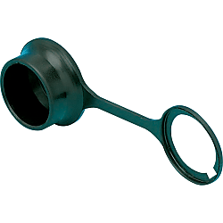
HR10 Dust-proof Cap
Cliquez sur cette image pour l'agrandir.
Cliquez sur cette image pour l'agrandir.
- Remise sur volume
A dust-proof cap to prevent contamination from foreign bodies and protect the connected portion

● Prevents intrusion of dust and foreign matter to the fitting surface when mounted on unused panel mount receptacle.

· Does not have waterproof functionality.
Référence pièce
Vous pouvez trouver ici le numéro
de référence lié au produit recherché.
HR10-10R-C
Spécifications

| Model | Number of Cores | Weight g |
| HR10-7R-C | 4,6 | 0.3 |
| HR10-10R-C | 10,12 | 0.6 |
Plus d'informations

Référence pièce
|
|---|
| HR10-10R-C |
| Référence pièce |
Prix unitaire standard
| Quantité minimale de commande | Remise sur volume | RoHS | |
|---|---|---|---|---|---|
1.91 € | 1 | Disponible | 5 jours | 10 |
Loading...
Characteristics
| Item | Contents |
|---|---|
| Rated Current | 2 A or lower |
| Rated Voltage | 14-core: 150 VAC / 200 VDC, Other: 100 VAC / 140 VDC |
| Withstand Voltage | 300 VAC or less (500 VAC or less for 4-core) / 1 minute |
| Insulation Resistance | 1,000 MΩ or more / 100 VDC |
| Contact Resistance | 10 mΩ or less / 1 ADC |
| Compatible Wire Size | AWG26 or below Loose Wires or 0.15 mm2 or less Loose Wires |
* For applicable wire size, cable finished outer diameter should be within cable clamp inner diameter.
Material / Finish
| Item | Materials | Finish |
|---|---|---|
| Body Shell | Zinc Alloy | Satin Nickel Plated |
| Pin Contact | Brass | Silver Plating |
| Socket Contact | Phosphor Bronze | Silver Plating |
| Insulator | Polyamide Resin | Black |

Contact Arrangement Diagram

Connection Work Method (Relay type can be done by the same method.)

| Number of Cores | Wrench Spacing (mm) | D Dimension (mm) | Wrench Tightening Force |
|---|---|---|---|
| 4.6 | 7.5 | 10 | 1.5 N・m (15 kgf・cm) |
| 10.12 | 9.5 | 16 | 1.5 N・m (15 kgf・cm) |
Connector Insertion and Removal Method

Vous vous trouvez sur la page de HR10 Dust-proof Cap, le numéro d'article est le suivant: HR10-10R-C.
Veuillez trouver plus de détails concernant les particularités et les dimensions sous le numéro d'article HR10-10R-C.
Configurer
Propriétés de base
-
Filtrer par type de données CAO
Filtrer par jours d'expédition standard
-
- Tous les articles
- 5 jours ou moins
Propriétés optionnelles
- Les spécifications et les dimensions de certaines pièces peuvent ne pas être intégralement indiquées. Pour plus de détails, reportez-vous aux catalogues des fabricants .
Assistance technique
Mode de paiement


Fabrication à la demande
Certificats


Copyright © MISUMI Corporation All Rights Reserved.