- Méthode de fonctionnement du cylindre
- Simple effet (rétraction)
- Simple effet spécial (rétraction par force externe)
- D.I. du cylindre : D(Ø)
- 32
- Port thread type
- Auto Switch
- Lead Wire Length(m)
- Number of Switches
- Type of Mount Support
- Custom-made Specifications
- Customized specification (port positions)
- Boulon de montage
- Type de connecteur
- Type
- CAO
- 2D
- 3D
- Jours d'expédition estimés
- Tout
- Dans les 26 jours ouvrables
RS(D)Q-Z, Vérin stoppeur à hauteur fixe (RSDQA32-20TDZ)

Informations sur le produit
Stopper Cylinder, Fixed Mounting Height RSQ Series Specifications
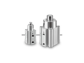
Round bar type external appearance
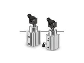
Lever type external appearance
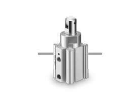
Roller type external appearance

Chamfered type external appearance
Specifications
| Tube Inner Diameter (mm) | 16 | 20 | 32 | 40 | 50 |
|---|---|---|---|---|---|
| Action | Double acting type, Double acting with spring type, Single acting spring extend type | ||||
| Fluid | Air | ||||
| Proof Pressure | 1.5 MPa | ||||
| Maximum operating pressure | 1.0 MPa | ||||
| Ambient and Fluid Temperature | Without auto switch: -10°C to 70°C (No freezing) With auto switch: -10°C to 60°C (No freezing) | ||||
| Lubrication | Not required (non-lubricated) | ||||
| Cushioning | Rubber cushion | ||||
| Stroke Length Tolerance | +1.4* 0 | ||||
| Piston Speed | 50 to 500 mm/s | ||||
| Mounting | Through bole / Both ends tapped | ||||
*The stroke length tolerance does not include bumper deflection.
Standard Stroke Table
(Units: mm)
| Tube Internal Diameter | Rod-End Configuration | |
|---|---|---|
| Round Bar Type, Chamfered Type, Roller Type | Lever Type | |
| 16 | 10, 15 | - |
| 20 | 10, 15, 20 | - |
| 32 | 10, 15, 20 | |
| 40 | 20, 25, 30 | 20, 25, 30 |
| 50 | ||
Spring Force (Single Acting Spring Extend Type)
(Unit: N)
| Tube Inner Diameter (mm) | Extended | Retracted |
|---|---|---|
| 16 | 4.9 | 14.9 |
| 20 | 3.4 | 14.9 |
| 32 | 8.8 | 18.6 |
| 40, 50 | 13.7 | 27.5 |
*Only applicable to round bar, chamfered and roller type end configurations.
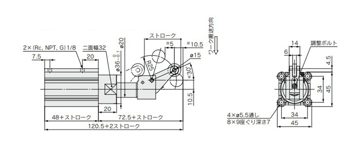
Dimensions
The figure shows an extended piston rod. The external dimensions of the double acting spring type and single acting spring extend type are the same as for the double acting type.
(Units: mm)
Rod-End Configuration: Lever Type (Fixed) / Through Hole Mounting
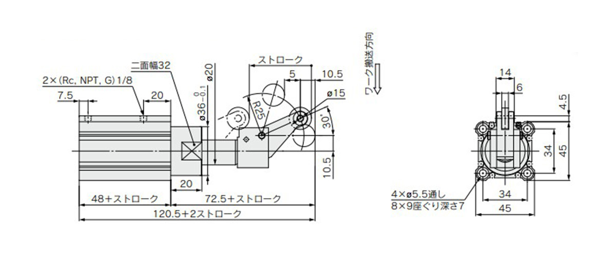
Tube internal diameter: 32 mm / RS□QB32□-□DLZ (double acting type)
Rod-End Configuration: Lever Type (Energy Absorbing Adjustable Type) / Through Hole Mounting
Tube internal diameter 32 mm / RS□QB32□-□DBZ (double acting type) dimensions
Rod-End Configuration: Lever Type (Energy Absorbing Adjustable Type), With Lock Mechanism / Through Hole Mounting
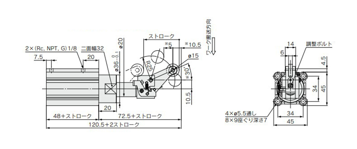
Tube internal diameter 32 mm / RS□QB32□-□DDZ (double acting type) dimensions
*See the manufacturer's catalog for product information other than that detailed above.
Precautions Regarding Dimensions
*1: For the single acting type, a one-touch fitting is on the rod end only.
*2: The position of the width across flats (K) is arbitrary and is not constant.
Rod-end configuration: Lever type (energy absorbing adjustable type) / Through hole mounting with lock mechanism / Through hole mounting only
*The drawing indicates the dimensions when the adjustment bolt is lowered (at maximum energy absorption). Dimensions with an asterisk (*) change when the adjustment bolt is raised (energy absorption is reduced).
ø32 mm: *30° → *20°, *10.5 → *9, *5 → *6
ø40 mm, ø50 mm: *24° → *16°, *13.5 → *11.5, *14 → *16
*See the manufacturer's catalog for product information other than that detailed above.
Plus d'informations
Informations de base
An air cylinder with abundant rod-end configurations. No mounting brackets required.
[Features]
· Female thread types are now available to have on the round bar and chamfered type rod ends.
· The use of a new body design allows for auto switches to be mounted on the 4 faces.
· The type can be selected to fit the application.
· Lever type can be selected to fit the application.
· Shock absorbers can easily be replaced.
· 3 mounting methods: Rod end tapped, head end tapped and through hole.
*See the SMC catalog for specification details.
*Product pictures are representative images.
Attention
- ■ Gamme de produits SMC
Les pages Web relatives aux produits qui ne possèdent pas de page spécifique sur ce site seront publiées au cas par cas. - Les images de produits peuvent être des images représentatives. Reportez-vous au catalogue pour plus de détails.