Broches de levage pour trous taraudés , autobloquantes
Cliquez sur cette image pour l'agrandir.
Cliquez sur cette image pour l'agrandir.
Toutes les versions sont résistantes à la corrosion. Le modèle en acier inoxydable est en outre résistant à la corrosion et aux intempéries, ce qui permet de l’utiliser en extérieur. La broche traitée et trempée par précipitation supporte des contraintes extrêmes.
[Fonctionnement]
Appuyer sur le bouton pour déverrouiller les éléments filetés.
Référence pièce
Vous pouvez trouver ici le numéro
de référence lié au produit recherché.
22352.0030
Threaded Lifting Pins • self-locking, EH 22352.
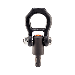
Product Description
 | Heavy-duty lifting element for quick and easy use, with moveable shackle and locking stud to provide protection against unintentional unlocking. For lifting loads, the threaded lifting pin is inserted into a threaded hole. In contrast to a ringbolt, time-consuming screwing in and out is therefore unnecessary. All versions are corrosion-protected. The version made of stainless steel is also resistant to corrosion and weathering, so it is also suitable for external use. In addition, the high-strength, precipitation-hardened pin makes extreme loads possible. |
Material
• Heat-treated steel, tempered, manganese phosphated
• Stainless steel 1.4542, precipitation-hardened
Press button
• Aluminium, orange, anodised
Threaded element
• Stainless steel 1.4542, precipitation-hardened
Shackle
• Heat-treated steel, tempered, manganese phosphated
• Stainless steel 1.4571
Spring
• Stainless steel
Assembly
Mounting:
1. Press in the button and hold it down.
2. Insert the threaded lifting pin.
3. Release the button (The button must be back in its original position.).
4. Tighten the threaded lifting pin by hand, until it bears completely on the bearing surface.
5. It must be ensured that the threaded segments are engaged in the mounting thread.
Dismantling:
1. Unscrew the threaded lifting pin approx. a quarter of a turn anticlockwise.
2. Press in the button and hold it down.
3. Remove the threaded lifting pin.
4. Release the button.
Operation
Further products
• Lifting Pins, self-locking, stainless steel
• Threaded Lifting Pins, self-locking, for centre holes according to DIN 332
• Threaded Lifting Pins, self-locking, with rotatable shackle
• Threaded Lifting Pins, self-locking - INCH
• Threaded Lifting Pins, self-locking, with rotatable shackle - INCH
Drawing

Order Information
| Dimensions | Load capacity1) | Locating thread | Operating temperature range max. | Weight | Art. No. | ||||||||||||||
| d1 | l1 | d2 | d3 | l2 | l3 | l4 | l5 | l6 | l7 | l8 | l9 | l10 | F1 | F2 | F3 | ||||
| -0.07 | |||||||||||||||||||
| [mm] | [kN] | [mm] | [°C] | [g] | |||||||||||||||
| Heat-treated steel | |||||||||||||||||||
| M 8 | 12 | 6.62 | 21.5 | 17.8 | 25.7 | 36 | 27.0 | 30.0 | 49 | 87.5 | 21.5 | 8 | 2.1 | 0.9 | 0.8 | M 8 | 250 | 274 | 22352.0008 |
| M10 | 14 | 8.35 | 21.5 | 20.0 | 25.7 | 36 | 27.0 | 30.0 | 49 | 87.5 | 21.5 | 10 | 3.9 | 1.5 | 1.5 | M10 | 250 | 268 | 22352.0010 |
| M12 | 17 | 10.07 | 21.5 | 24.0 | 25.7 | 36 | 27.0 | 30.0 | 49 | 87.5 | 21.5 | 12 | 6.2 | 2.5 | 2.3 | M12 | 250 | 273 | 22352.0012 |
| M14 | 17 | 11.80 | 21.5 | 24.0 | 25.7 | 36 | 27.0 | 30.0 | 49 | 87.5 | 21.5 | 12 | 7.8 | 4.2 | 2.9 | M14 | 250 | 279 | 22352.0014 |
| M16 | 17 | 13.80 | 21.5 | 24.0 | 25.7 | 36 | 27.0 | 30.0 | 49 | 87.5 | 21.5 | 12 | 8.4 | 4.5 | 4.2 | M16 | 250 | 284 | 22352.0016 |
| M20 | 22 | 17.25 | 30.0 | 30.0 | 36.5 | 52 | 32.6 | 36.0 | 56 | 114.0 | 26.0 | 17 | 16.6 | 7.7 | 5.8 | M20 | 250 | 586 | 22352.0020 |
| M24 | 27 | 20.70 | 36.0 | 36.0 | 42.0 | 60 | 50.6 | 49.8 | 82 | 152.0 | 36.0 | 22 | 23.0 | 11.1 | 8.6 | M24 | 250 | 1187 | 22352.0024 |
| M27 | 31 | 23.67 | 45.0 | 40.0 | 42.0 | 60 | 50.6 | 49.8 | 82 | 152.0 | 36.0 | 26 | 33.8 | 15.7 | 13.7 | M27 | 250 | 1546 | 22352.0027 |
| M30 | 35 | 26.10 | 45.0 | 45.0 | 42.0 | 60 | 50.6 | 49.8 | 82 | 152.0 | 36.0 | 30 | 42.3 | 21.5 | 15.5 | M30 | 250 | 1596 | 22352.0030 |
| Stainless steel | |||||||||||||||||||
| M 8 | 12 | 6.62 | 21.5 | 17.8 | 25.7 | 36 | 27.0 | 30.0 | 49 | 87.5 | 21.5 | 8 | 2.1 | 0.9 | 0.8 | M 8 | 250 | 228 | 22352.1008 |
| M10 | 14 | 8.35 | 21.5 | 20.0 | 25.7 | 36 | 27.0 | 30.0 | 49 | 87.5 | 21.5 | 10 | 3.9 | 1.5 | 1.5 | M10 | 250 | 273 | 22352.1010 |
| M12 | 17 | 10.07 | 21.5 | 24.0 | 25.7 | 36 | 27.0 | 30.0 | 49 | 87.5 | 21.5 | 12 | 6.2 | 2.5 | 2.3 | M12 | 250 | 286 | 22352.1012 |
| M16 | 17 | 13.80 | 21.5 | 24.0 | 25.7 | 36 | 27.0 | 30.0 | 49 | 87.5 | 21.5 | 12 | 8.4 | 4.5 | 4.2 | M16 | 250 | 247 | 22352.1016 |
| M20 | 22 | 17.25 | 30.0 | 30.0 | 36.5 | 52 | 32.6 | 36.0 | 56 | 114.0 | 26.0 | 17 | 10.0 | 7.7 | 5.8 | M20 | 250 | 519 | 22352.1020 |
| M24 | 27 | 20.70 | 36.0 | 36.0 | 42.0 | 60 | 50.6 | 49.8 | 82 | 152.0 | 36.0 | 22 | 23.0 | 11.1 | 8.6 | M24 | 250 | 1219 | 22352.1024 |
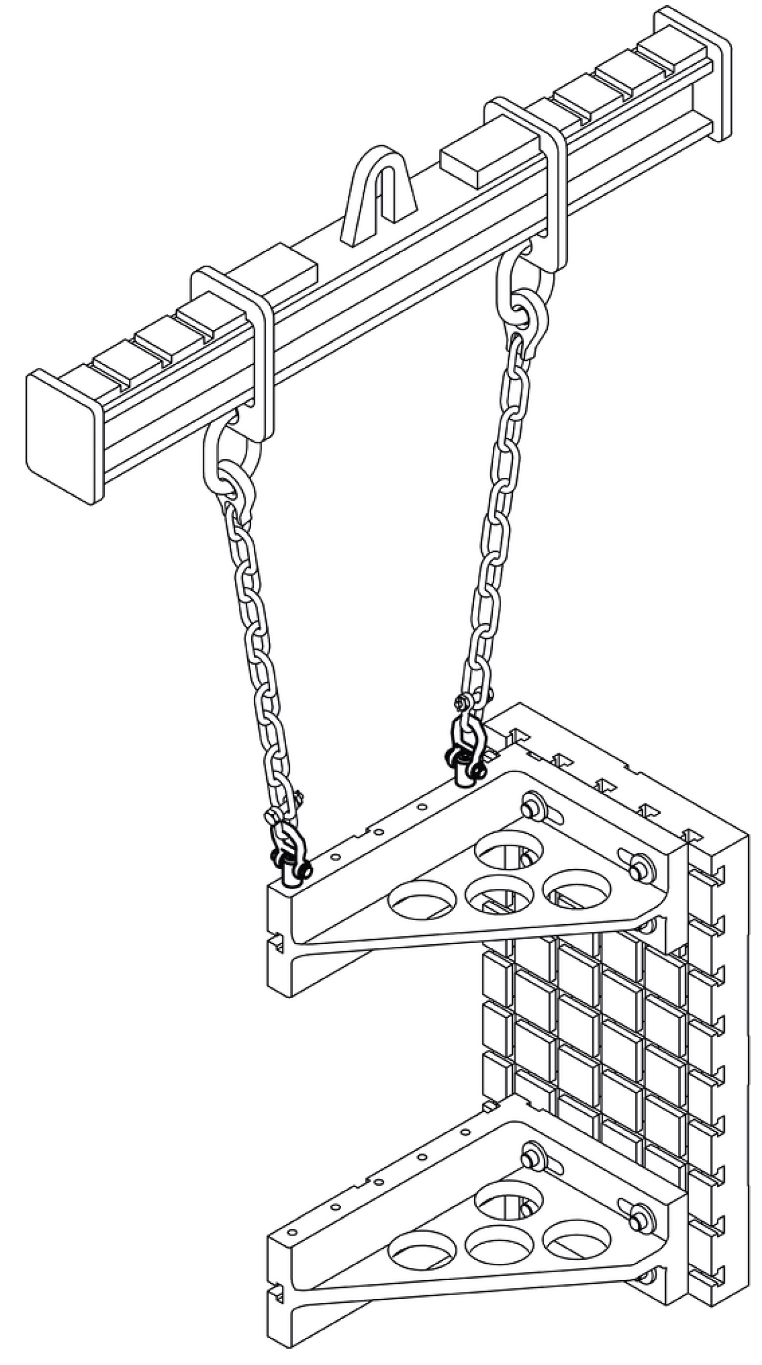
Application Example


Référence pièce
|
|---|
| 22352.0030 |
| Référence pièce | Relatif à |
Prix unitaire standard
| Quantité minimale de commande | Remise sur volume | Vis nominale (M) | d2 (mm) | d3 (mm) | l1 (mm) | l2 (mm) | l3 (mm) | l4 (mm) | l5 (mm) | l6 (mm) | l7 (mm) | l8 (mm) | l9 (mm) | l10 (mm) | F1 (kN) | F2 (kN) | F3 (kN) | Taraudage (mm) | Axe | Manilles | Poids (g) | |
|---|---|---|---|---|---|---|---|---|---|---|---|---|---|---|---|---|---|---|---|---|---|---|---|---|---|
348.09 € | 1 | 3 jours | M30 | 26.1 | 45 | 35.0 | 45.0 | 42.0 | 60.0 | 50.6 | 49.8 | 82.0 | 152.0 | 36.0 | 30.0 | 42.3 | 21.5 | 15.5 | M30 | acier traité | acier traité | 1596 |
Loading...
Informations de base
| Température max(°C) | 250 | Bouton-poussoir | aluminium, anodisé orange | Éléments filetés | inox 1.4542 |
|---|---|---|---|---|---|
| Ressort | inox |
Vous vous trouvez sur la page de Broches de levage pour trous taraudés , autobloquantes, le numéro d'article est le suivant: 22352.0030.
Veuillez trouver plus de détails concernant les particularités et les dimensions sous le numéro d'article 22352.0030.
Configurer
Propriétés de base
-
d2(mm)
-
d3(mm)
-
l1(mm)
- 17.0
- 22.0
- 27.0
- 31
- 35.0
-
l2(mm)
- 24.0
- 30.0
- 36.0
- 40.0
- 45.0
-
l3(mm)
- 25.7
- 36.5
- 42.0
-
l4(mm)
-
l5(mm)
- 27.0
- 32.6
- 50.6
-
l6(mm)
- 30.0
- 36.0
- 49.8
-
l7(mm)
- 49.0
- 56.0
- 82.0
-
l8(mm)
-
l9(mm)
- 21.5
- 26.0
- 36.0
-
l10(mm)
- 12.0
- 17.0
- 22.0
- 26.0
- 30.0
-
F1(kN)
-
F2(kN)
- 4.2
- 7.7
- 11.1
- 15.7
- 21.5
-
F3(kN)
- 2.9
- 5.8
- 8.6
- 13.7
- 15.5
-
Taraudage(mm)
- M14
- M20
- M24
- M27
- M30
-
Axe
- inox 1.4542
- acier traité
-
Manilles
- inox 1.4571
- acier traité
-
Type
- 22352
-
Vis nominale (M)
-
Filtrer par type de données CAO
Filtrer par jours d'expédition standard
-
- Tous les articles
- 2 jours ou moins
- 3 jours ou moins
Propriétés optionnelles
- Les spécifications et les dimensions de certaines pièces peuvent ne pas être intégralement indiquées. Pour plus de détails, reportez-vous aux catalogues des fabricants .
Variantes de ce produit
| Référence pièce |
|---|
| 22352.0016 |
| 22352.0020 |
| 22352.0024 |
| 22352.1010 |
| 22352.1012 |
| 22352.1016 |
| Référence pièce | Relatif à | Prix unitaire standard | Quantité minimale de commande | Remise sur volume | Jour d'expédition standard ? | Vis nominale (M) | d2 (mm) | d3 (mm) | l1 (mm) | l2 (mm) | l3 (mm) | l4 (mm) | l5 (mm) | l6 (mm) | l7 (mm) | l8 (mm) | l9 (mm) | l10 (mm) | F1 (kN) | F2 (kN) | F3 (kN) | Taraudage (mm) | Axe | Manilles | Poids (g) |
|---|---|---|---|---|---|---|---|---|---|---|---|---|---|---|---|---|---|---|---|---|---|---|---|---|---|
196.63 € | 1 | 2 jours | - | - | - | - | - | - | - | - | - | - | - | - | - | - | - | - | - | - | - | - | |||
216.86 € | 1 | 3 jours | M20 | 17.25 | 30 | 22.0 | 30.0 | 36.5 | 52.0 | 32.6 | 36.0 | 56.0 | 114.0 | 26.0 | 17.0 | 16.6 | 7.7 | 5.8 | M20 | acier traité | acier traité | 586 | |||
269.98 € | 1 | 3 jours | M24 | 20.7 | 36 | 27.0 | 36.0 | 42.0 | 60.0 | 50.6 | 49.8 | 82.0 | 152.0 | 36.0 | 22.0 | 23.0 | 11.1 | 8.6 | M24 | acier traité | acier traité | 1187 | |||
244.28 € | 1 | 2 jours | - | - | - | - | - | - | - | - | - | - | - | - | - | - | - | - | - | - | - | - | |||
251.49 € | 1 | 2 jours | - | - | - | - | - | - | - | - | - | - | - | - | - | - | - | - | - | - | - | - | |||
256.12 € | 1 | 2 jours | - | - | - | - | - | - | - | - | - | - | - | - | - | - | - | - | - | - | - | - |


