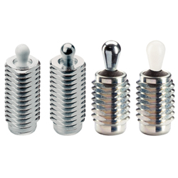
Poussoirs latéraux, avec filetage (22150.0420)
Détails du produit:
Référence fabricant: 22150.0420
Marque: HALDER
Prix: 9.05 €
Délai de livraison: 4 jours
Données techniques:
d1: M12 mm
d2: 5 mm
l1: 26.5 mm
l2: 6 mm
Spring Load F max.: ~ 100 N
Référence pièce
Vous pouvez trouver ici le numéro
de référence lié au produit recherché.
22150.0420
Lateral Plungers • with thread, without seal, EH 22150.
Product Description
 | To be used for positioning and applying pressure, e.g. during painting and sandblasting. |
Material
• Steel, zinc-plated by galvanization
Spring
• Stainless steel
• Steel, blackened
• Steel, zinc-plated by galvanization
Pin
• Steel, case-hardened, zinc-plated by galvanization
• Thermoplastic POM, white
Assembly
Formula for calculating the center distance for the mounting hole:
l0 = z/2 + w + x,
l0 = center distance,
y = workpiece height,
w = workpiece length,
x = coordinate dimension,
s = stroke,
z = stop diameter
Calculation dimension x:
y greater than or equal to l2 - d2/2,
then x = d2/2 - s
or
y smaller than l2 - d2/2,
then x = d2/2 - s - [(l2 - d2/2 - y) * 0.123]
Characteristic
Version standard spring load = spring from steel, blackened
Version heavy spring load = spring from steel, zinc-plated by galvanization
Drawing

Order Information
| Dimensions | Spring load | Dimensions | Stroke | WS | Operating temperature range | Weight | Art. No. | ||
| d1 | l1 | F | d2 | l2 | s | max. | |||
| -2 | max. 1) | ||||||||
| ~ | |||||||||
| [mm] | [N] | [mm] | [mm] | [mm] | [°C] | [g] | |||
| Pin: Steel/Light spring load | |||||||||
| M12 | 11.5 | 20 | 5 | 6.4 | 1.6 | 10 | 250 | 4.0 | 22150.0310 |
| M12 | 19.0 | 20 | 5 | 6.4 | 1.6 | 10 | 250 | 5.9 | 22150.0314 |
| M12 | 26.5 | 20 | 5 | 6.4 | 1.6 | 10 | 250 | 7.9 | 22150.0318 |
| M12 | 11.5 | 40 | 6 | 10.4 | 2.0 | 10 | 250 | 4.8 | 22150.0330 |
| M12 | 19.0 | 40 | 6 | 10.4 | 2.0 | 10 | 250 | 6.6 | 22150.0334 |
| M12 | 26.5 | 40 | 6 | 10.4 | 2.0 | 10 | 250 | 8.6 | 22150.0338 |
| M18 x 1,5 | 18.0 | 100 | 10 | 16.9 | 3.2 | 16 | 250 | 19.0 | 22150.0350 |
| M18 x 1,5 | 31.5 | 100 | 10 | 16.9 | 3.2 | 16 | 250 | 28.0 | 22150.0354 |
| M18 x 1,5 | 45.0 | 100 | 10 | 16.9 | 3.2 | 16 | 250 | 36.0 | 22150.0358 |
| Pin: Steel/Standard spring load | |||||||||
| M12 | 11.5 | 50 | 5 | 6.4 | 1.6 | 10 | 250 | 4.1 | 22150.0311 |
| M12 | 19.0 | 50 | 5 | 6.4 | 1.6 | 10 | 250 | 6.4 | 22150.0315 |
| M12 | 26.5 | 50 | 5 | 6.4 | 1.6 | 10 | 250 | 8.3 | 22150.0319 |
| M12 | 11.5 | 75 | 6 | 10.4 | 2.0 | 10 | 250 | 4.9 | 22150.0331 |
| M12 | 19.0 | 75 | 6 | 10.4 | 2.0 | 10 | 250 | 7.1 | 22150.0335 |
| M12 | 26.5 | 75 | 6 | 10.4 | 2.0 | 10 | 250 | 9.6 | 22150.0339 |
| M18 x 1,5 | 18.0 | 150 | 10 | 16.9 | 3.2 | 16 | 250 | 20.0 | 22150.0351 |
| M18 x 1,5 | 31.5 | 150 | 10 | 16.9 | 3.2 | 16 | 250 | 29.0 | 22150.0355 |
| M18 x 1,5 | 45.0 | 150 | 10 | 16.9 | 3.2 | 16 | 250 | 39.0 | 22150.0359 |
| Pin: Steel/Heavy spring load | |||||||||
| M12 | 11.5 | 100 | 5 | 6.4 | 1.6 | 10 | 250 | 4.4 | 22150.0312 |
| M12 | 19.0 | 100 | 5 | 6.4 | 1.6 | 10 | 250 | 6.9 | 22150.0316 |
| M12 | 26.5 | 100 | 5 | 6.4 | 1.6 | 10 | 250 | 9.0 | 22150.0320 |
| M12 | 11.5 | 100 | 6 | 10.4 | 2.0 | 10 | 250 | 5.4 | 22150.0332 |
| M12 | 19.0 | 100 | 6 | 10.4 | 2.0 | 10 | 250 | 7.7 | 22150.0336 |
| M12 | 26.5 | 100 | 6 | 10.4 | 2.0 | 10 | 250 | 10.0 | 22150.0340 |
| M18 x 1,5 | 18.0 | 200 | 10 | 16.9 | 3.2 | 16 | 250 | 21.0 | 22150.0352 |
| M18 x 1,5 | 31.5 | 200 | 10 | 16.9 | 3.2 | 16 | 250 | 30.0 | 22150.0356 |
| M18 x 1,5 | 45.0 | 200 | 10 | 16.9 | 3.2 | 16 | 250 | 40.0 | 22150.0360 |
| Pin: Thermoplastic/Light spring load | |||||||||
| M12 | 11.5 | 20 | 5 | 6.4 | 1.6 | 10 | 80 | 2.7 | 22150.0370 |
| M12 | 19.0 | 20 | 5 | 6.4 | 1.6 | 10 | 80 | 4.6 | 22150.0375 |
| M12 | 26.5 | 20 | 5 | 6.4 | 1.6 | 10 | 80 | 6.5 | 22150.0383 |
| M12 | 11.5 | 40 | 6 | 10.4 | 2.0 | 10 | 80 | 3.1 | 22150.0373 |
| M12 | 19.0 | 40 | 6 | 10.4 | 2.0 | 10 | 80 | 4.8 | 22150.0380 |
| M12 | 26.5 | 40 | 6 | 10.4 | 2.0 | 10 | 80 | 6.8 | 22150.0385 |
| M18 x 1,5 | 18.0 | 100 | 10 | 16.9 | 3.2 | 16 | 80 | 12.0 | 22150.0390 |
| M18 x 1,5 | 31.5 | 100 | 10 | 16.9 | 3.2 | 16 | 80 | 20.0 | 22150.0393 |
| M18 x 1,5 | 45.0 | 100 | 10 | 16.9 | 3.2 | 16 | 80 | 30.0 | 22150.0395 |
Accessories
| Dimensions | Weight | Art. No. | |
| d1 | |||
| [mm] | [g] | ||
| Assembly Tool | |||
 | M12 | 76 | 22150.0820 |
| M18 x 1,5 | 137 | 22150.0822 | |
Application Example

Lateral Plungers • with thread, with seal, EH 22150.
Product Description
 | To be used for positioning and applying pressure, e.g. during painting and sandblasting. Sealed against chips and dirt. |
Material
• CR
Body
• Steel, zinc-plated by galvanization
Spring
• Stainless steel
• Steel, blackened
• Steel, zinc-plated by galvanization
Pin
• Steel, case-hardened, zinc-plated by galvanization
• Thermoplastic POM, white
Assembly
Formula for calculating the center distance for the mounting hole:
l0 = z/2 + w + x,
l0 = center distance,
y = workpiece height,
w = workpiece length,
x = coordinate dimension,
s = stroke,
z = stop diameter
Calculation dimension x:
y greater than or equal to l2 - d2/2,
then x = d2/2 - s
or
y smaller than l2 - d2/2,
then x = d2/2 - s - [(l2 - d2/2 - y) * 0.123]
Characteristic
Version standard spring load = spring from steel, blackened
Version heavy spring load = spring from steel, zinc-plated by galvanization
Drawing

Order Information
| Dimensions | Spring load | Dimensions | Stroke | WS | Operating temperature range | Weight | Art. No. | ||
| d1 | l1 | F | d2 | l2 | s | max. | |||
| -2 | max. 1) | ||||||||
| ~ | |||||||||
| [mm] | [N] | [mm] | [mm] | [mm] | [°C] | [g] | |||
| Pin: Steel/Light spring load | |||||||||
| M12 | 11.5 | 20 | 5 | 6 | 0.8 | 10 | 110 | 3.8 | 22150.0410 |
| M12 | 19.0 | 20 | 5 | 6 | 0.8 | 10 | 110 | 5.6 | 22150.0414 |
| M12 | 26.5 | 20 | 5 | 6 | 0.8 | 10 | 110 | 7.5 | 22150.0418 |
| M12 | 11.5 | 40 | 6 | 10 | 1.0 | 10 | 110 | 4.7 | 22150.0430 |
| M12 | 19.0 | 40 | 6 | 10 | 1.0 | 10 | 110 | 6.5 | 22150.0434 |
| M12 | 26.5 | 40 | 6 | 10 | 1.0 | 10 | 110 | 8.3 | 22150.0438 |
| M18 x 1,5 | 18.0 | 100 | 10 | 16 | 1.6 | 16 | 110 | 20.0 | 22150.0450 |
| M18 x 1,5 | 31.5 | 100 | 10 | 16 | 1.6 | 16 | 110 | 28.0 | 22150.0454 |
| M18 x 1,5 | 45.0 | 100 | 10 | 16 | 1.6 | 16 | 110 | 36.0 | 22150.0458 |
| Pin: Steel/Standard spring load | |||||||||
| M12 | 11.5 | 50 | 5 | 6 | 0.8 | 10 | 110 | 4.1 | 22150.0411 |
| M12 | 19.0 | 50 | 5 | 6 | 0.8 | 10 | 110 | 6.3 | 22150.0415 |
| M12 | 26.5 | 50 | 5 | 6 | 0.8 | 10 | 110 | 8.1 | 22150.0419 |
| M12 | 11.5 | 75 | 6 | 10 | 1.0 | 10 | 110 | 4.8 | 22150.0431 |
| M12 | 19.0 | 75 | 6 | 10 | 1.0 | 10 | 110 | 6.9 | 22150.0435 |
| M12 | 26.5 | 75 | 6 | 10 | 1.0 | 10 | 110 | 8.9 | 22150.0439 |
| M18 x 1,5 | 18.0 | 150 | 10 | 16 | 1.6 | 16 | 110 | 20.0 | 22150.0451 |
| M18 x 1,5 | 31.5 | 150 | 10 | 16 | 1.6 | 16 | 110 | 29.0 | 22150.0455 |
| M18 x 1,5 | 45.0 | 150 | 10 | 16 | 1.6 | 16 | 110 | 40.0 | 22150.0459 |
| Pin: Steel/Heavy spring load | |||||||||
| M12 | 11.5 | 100 | 5 | 6 | 0.8 | 10 | 110 | 4.2 | 22150.0412 |
| M12 | 19.0 | 100 | 5 | 6 | 0.8 | 10 | 110 | 6.6 | 22150.0416 |
| M12 | 26.5 | 100 | 5 | 6 | 0.8 | 10 | 110 | 8.7 | 22150.0420 |
| M12 | 11.5 | 100 | 6 | 10 | 1.0 | 10 | 110 | 5.4 | 22150.0432 |
| M12 | 19.0 | 100 | 6 | 10 | 1.0 | 10 | 110 | 7.6 | 22150.0436 |
| M12 | 26.5 | 100 | 6 | 10 | 1.0 | 10 | 110 | 10.0 | 22150.0440 |
| M18 x 1,5 | 18.0 | 200 | 10 | 16 | 1.6 | 16 | 110 | 20.0 | 22150.0452 |
| M18 x 1,5 | 31.5 | 200 | 10 | 16 | 1.6 | 16 | 110 | 29.0 | 22150.0456 |
| M18 x 1,5 | 45.0 | 200 | 10 | 16 | 1.6 | 16 | 110 | 38.0 | 22150.0460 |
| Pin: Thermoplastic/Light spring load | |||||||||
| M12 | 11.5 | 20 | 5 | 6 | 0.8 | 10 | 80 | 2.6 | 22150.0470 |
| M12 | 19.0 | 20 | 5 | 6 | 0.8 | 10 | 80 | 4.4 | 22150.0475 |
| M12 | 26.5 | 20 | 5 | 6 | 0.8 | 10 | 80 | 6.1 | 22150.0483 |
| M12 | 11.5 | 40 | 6 | 10 | 1.0 | 10 | 80 | 2.7 | 22150.0473 |
| M12 | 19.0 | 40 | 6 | 10 | 1.0 | 10 | 80 | 4.5 | 22150.0480 |
| M12 | 26.5 | 40 | 6 | 10 | 1.0 | 10 | 80 | 6.2 | 22150.0485 |
| M18 x 1,5 | 18.0 | 100 | 10 | 16 | 1.6 | 16 | 80 | 12.0 | 22150.0490 |
| M18 x 1,5 | 31.5 | 100 | 10 | 16 | 1.6 | 16 | 80 | 21.0 | 22150.0493 |
| M18 x 1,5 | 45.0 | 100 | 10 | 16 | 1.6 | 16 | 80 | 30.0 | 22150.0495 |
Accessories
| Dimensions | Weight | Art. No. | |
| d1 | |||
| [mm] | [g] | ||
| Assembly Tool | |||
 | M12 | 76 | 22150.0820 |
| M18 x 1,5 | 137 | 22150.0822 | |
Application Example

Référence pièce
|
|---|
| 22150.0420 |
| Référence pièce | Relatif à |
Prix unitaire standard
| Quantité minimale de commande | Remise sur volume | RoHS | d1 (mm) | d2 (mm) | l1 (mm) | l2 (mm) | Spring Load F max. (N) | Temperature max. (°C) | WS (mm) | Spring | Pin | Seal | |
|---|---|---|---|---|---|---|---|---|---|---|---|---|---|---|---|---|
9.05 € | 1 | 4 jours | 10 | M12 | 5 | 26.5 | 6 | ~ 100 | 110 | 10 | Steel, galvanized | Steel, case-hardened, galvanized | CR |
Loading...
Informations de base
| Conflict Minerals free | yes | REACH compliant | yes |
|---|
Vous vous trouvez sur la page de Poussoirs latéraux, avec filetage, le numéro d'article est le suivant: 22150.0420.
Veuillez trouver plus de détails concernant les particularités et les dimensions sous le numéro d'article 22150.0420.
Configurer
Propriétés de base
-
Type
- 22150
-
d1(mm)
- M12
- M18 x 1,5
-
d2(mm)
- 5
- 6
- 10
-
l1(mm)
-
l2(mm)
-
Spring Load F max.(N)
- ~ 20
- ~ 40
- ~ 50
- ~ 75
- ~ 100
- ~ 150
- ~ 200
-
Temperature max.(°C)
- 80
- 110
- 250
-
WS(mm)
- 10
- 16
-
Spring
- Stainless steel
- Steel, blackened
- Steel, galvanized
-
Pin
- Steel, case-hardened, galvanized
- Thermoplastic POM, white
-
Seal
-
Filtrer par type de données CAO
Filtrer par jours d'expédition standard
-
- Tous les articles
- Jour même
- 2 jours ou moins
- 4 jours ou moins
Propriétés optionnelles
- Les spécifications et les dimensions de certaines pièces peuvent ne pas être intégralement indiquées. Pour plus de détails, reportez-vous aux catalogues des fabricants .
Variantes de ce produit
| Référence pièce |
|---|
| 22150.0314 |
| 22150.0315 |
| 22150.0316 |
| 22150.0430 |
| 22150.0431 |
| 22150.0432 |
| Référence pièce | Relatif à | Prix unitaire standard | Quantité minimale de commande | Remise sur volume | Jour d'expédition standard ? | RoHS | d1 (mm) | d2 (mm) | l1 (mm) | l2 (mm) | Spring Load F max. (N) | Temperature max. (°C) | WS (mm) | Spring | Pin | Seal |
|---|---|---|---|---|---|---|---|---|---|---|---|---|---|---|---|---|
7.94 € | 1 |
Jour même
Stock | 10 | M12 | 5 | 19 | 6.7 | ~ 20 | 250 | 10 | Stainless steel | Steel, case-hardened, galvanized | - | |||
7.94 € | 1 | 4 jours | 10 | M12 | 5 | 19 | 6.7 | ~ 50 | 250 | 10 | Steel, blackened | Steel, case-hardened, galvanized | - | |||
7.94 € | 1 | 4 jours | 10 | M12 | 5 | 19 | 6.7 | ~ 100 | 250 | 10 | Steel, galvanized | Steel, case-hardened, galvanized | - | |||
8.64 € | 1 | 4 jours | 10 | M12 | 6 | 11.5 | 10 | ~ 40 | 110 | 10 | Stainless steel | Steel, case-hardened, galvanized | CR | |||
8.64 € | 1 |
Jour même
Stock | 10 | M12 | 6 | 11.5 | 10 | ~ 75 | 110 | 10 | Steel, blackened | Steel, case-hardened, galvanized | CR | |||
8.64 € | 1 | 4 jours | 10 | M12 | 6 | 11.5 | 10 | ~ 100 | 110 | 10 | Steel, galvanized | Steel, case-hardened, galvanized | CR |
Assistance technique
Mode de paiement


Fabrication à la demande
Certificats


Copyright © MISUMI Corporation All Rights Reserved.