Actionneurs linéaires / Actionneur électrique à curseur avec entraînement par courroie Série LEFB Moteur pas à pas/Servomoteur (LEFB16T-300-R11P1)
Détails du produit:
Référence fabricant: LEFB16T-300-R11P1
Marque: SMC
Prix: 1,394.23 €
Délai de livraison: 26 jours
Données techniques:
Stroke: 300 mm
Max. Transportable Mass Range (Horizontal): 0 à 2.0 kg
Max. Transportable Mass (Horizontal): 1 kg
Lead: 48 mm
I/O Module: PNP
(i)Remarque
- Les pages Web des produits qui ne disposent actuellement pas de pages individuelles sur ce site seront publiées de manière ponctuelle.
- Les images de produits peuvent être uniquement des images représentatives. Reportez-vous au catalogue du fabricant pour les détails de forme.
- Les données CAO ne sont pas disponibles pour certains numéros de modèle.
Référence pièce
Vous pouvez trouver ici le numéro
de référence lié au produit recherché.
LEFB16T-300-R11P1
Electric Actuator, Slider Type, Belt Drive LEFB Series Specifications

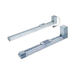
Electric Actuator, Slider Type, Belt Drive LEFB Series external appearance
Specifications / Step Motor (24‑V DC Servo)
| Model | LEFB16 | LEFB25 | LEFB32 | |||
|---|---|---|---|---|---|---|
| Actuator Specifications | Stroke [mm] Note 1: | 300, 500, 600, 700 800, 900, 1,000 | 300, 500, 600, 700, 800, 900 1,000, 1,200, 1,500, 1,800, 2,000 | 300, 500, 600, 700, 800, 900 1,000, 1,200, 1,500, 1,800, 2,000 | ||
| Work Load [kg] Note 2: | Horizontal | LECP6/LECP1/LECPMJ JXCE1/91/P1/D1 | 1 | 10 | 19 | |
| LECPA | 1 | 5 | 14 | |||
| Speed [mm/s] Note 2: | 48 to 1,100 | 48 to 1,400 | 48 to 1,500 | |||
| Maximum Acceleration/Deceleration [mm/s2] | 3,000 | |||||
| Positioning Repeatability [mm] | ±0.08 | |||||
| Lost Motion [mm] Note 3: | 0.1 or less | |||||
| Lead [mm] | 48 | 48 | 48 | |||
| Impact/Vibration Resistance [m/s2] Note 4: | 50/20 | |||||
| Actuation Type | Belt | |||||
| Guide Type | Linear guide | |||||
| Operating Temperature Range [°C] | 5 to 40 | |||||
| Operating Humidity Range [%RH] | 90 or less (no condensation) | |||||
| Electrical Specifications | Motor Size | □28 | □42 | □56.4 | ||
| Motor type | Step motor (24‑V DC servo) | |||||
| Encoder | Incremental A/B phase (800 pulses/rotation) | |||||
| Rated Voltage [V] | 24 DC ±10% | |||||
| Power Consumption [W] Note 5: | 24 | 32 | 52 | |||
| Standby Power Consumption When Operating [W] Note 6: | 18 | 16 | 44 | |||
| Maximum Instantaneous Power Consumption [W] Note 7: | 51 | 60 | 127 | |||
| Lock Specifications | Type Note 8: | Non-excitation operation (non-magnetizing lock) | ||||
| Holding Force [N] | 4 | 19 | 36 | |||
| Power Consumption [W] Note 9: | 2.9 | 5 | 5 | |||
| Rated Voltage [V] | 24 DC ±10% | |||||
Note 1: Non-standard strokes are manufactured as custom orders.
Note 2: The speed changes according to the controller/driver type and work load. See p. 41 of the SMC catalog ("Speed−Work Load Graph (Guide)") for more details. Furthermore, if the cable length exceeds 5 m, then it will decrease by up to 10% for each 5 m. Cannot be used vertically.
Note 3: A reference value for correcting an error in reciprocal operation.
Note 4: Impact resistance: No malfunction occurred when the actuator was tested with a drop tester in both an axial direction and a perpendicular direction to the lead screw. (Test was performed with the actuator in the initial state.)
Vibration resistance: No malfunction occurred in a test ranging between 45 and 2,000 Hz (1 sweep), performed in both an axial direction and a perpendicular direction to the lead screw. (Test was performed with the actuator in the initial state.)
Note 5: The power consumption (including the controller) is for when the actuator is operating.
Note 6: The standby power consumption when operating (including the controller) is for when the actuator is stopped in the set position during operation.
Note 7: The maximum instantaneous power consumption (including the controller) is for when the actuator is operating. This value can be used for selecting the power supply capacity.
Note 8: With lock only.
Note 9: For an actuator with a lock, add the power consumption for the lock.
Specifications / Servo Motor (24 V DC)
| Model | LEFB16A | LEFB25A | ||
|---|---|---|---|---|
| Actuator Specifications | Stroke [mm] Note 1: | 300, 500, 600, 700 800, 900, 1,000 | 300, 500, 600, 700, 800, 900 1,000, 1,200, 1,500, 1,800, 2,000 | |
| Work Load [kg] Note 2: | Horizontal | 1 | 2 | |
| Speed [mm/s] Note 2: | 5 to 2,000 | 5 to 2,000 | ||
| Maximum Acceleration/Deceleration [mm/s2] | 3,000 | |||
| Positioning Repeatability [mm] | ±0.08 | |||
| Lost Motion [mm] Note 3: | 0.1 or less | |||
| Lead [mm] | 48 | 48 | ||
| Impact/Vibration Resistance [m/s2] Note 4: | 50/20 | |||
| Actuation Type | Belt | |||
| Guide Type | Linear guide | |||
| Operating Temperature Range [°C] | 5 to 40 | |||
| Operating Humidity Range [%RH] | 90 or less (no condensation) | |||
| Electrical Specifications | Motor Size | □28 | □42 | |
| Motor Output [W] | 30 | 36 | ||
| Motor type | Servo motor (24 V DC) | |||
| Encoder | Incremental A/B (800 pulses/rotation) / Z phase | |||
| Rated Voltage [V] | 24 DC ±10% | |||
| Power Consumption [W] Note 5: | 78 | 69 | ||
| Standby Power Consumption When Operating [W] Note 6: | Horizontal 4 | Horizontal 5 | ||
| Maximum Instantaneous Power Consumption [W] Note 7: | 87 | 120 | ||
| Lock Specifications | Type Note 8: | Non-excitation operation (non-magnetizing lock) | ||
| Holding Force [N] | 4 | 19 | ||
| Power Consumption [W] Note 9: | 2.9 | 5 | ||
| Rated Voltage [V] | 24 DC ±10% | |||
Note 1: Non-standard strokes are manufactured as custom orders.
Note 2: See p. 42 of the SMC catalog ("Speed−Work Load Graph (Guide)") for more details. Furthermore, if the cable length exceeds 5 m, then it will decrease by up to 10% for each 5 m.
Note 3: A reference value for correcting an error in reciprocal operation.
Note 4: Impact resistance: No malfunction occurred when the actuator was tested with a drop tester in both an axial direction and a perpendicular direction to the lead screw. (Test was performed with the actuator in the initial state.)
Vibration resistance: No malfunction occurred in a test ranging between 45 and 2,000 Hz (1 sweep), performed in both an axial direction and a perpendicular direction to the lead screw. (Test was performed with the actuator in the initial state.)
Note 5: The power consumption (including the controller) is for when the actuator is operating.
Note 6: The standby power consumption when operating (including the controller) is for when the actuator is stopped in the set position while operating with maximum load.
Note 7: The maximum instantaneous power consumption (including the controller) is for when the actuator is operating. This value can be used for selecting the power supply capacity.
Note 8: With lock only.
Note 9: For an actuator with a lock, add the power consumption for the lock.
Dimensions / Belt Drive
(Units: mm)
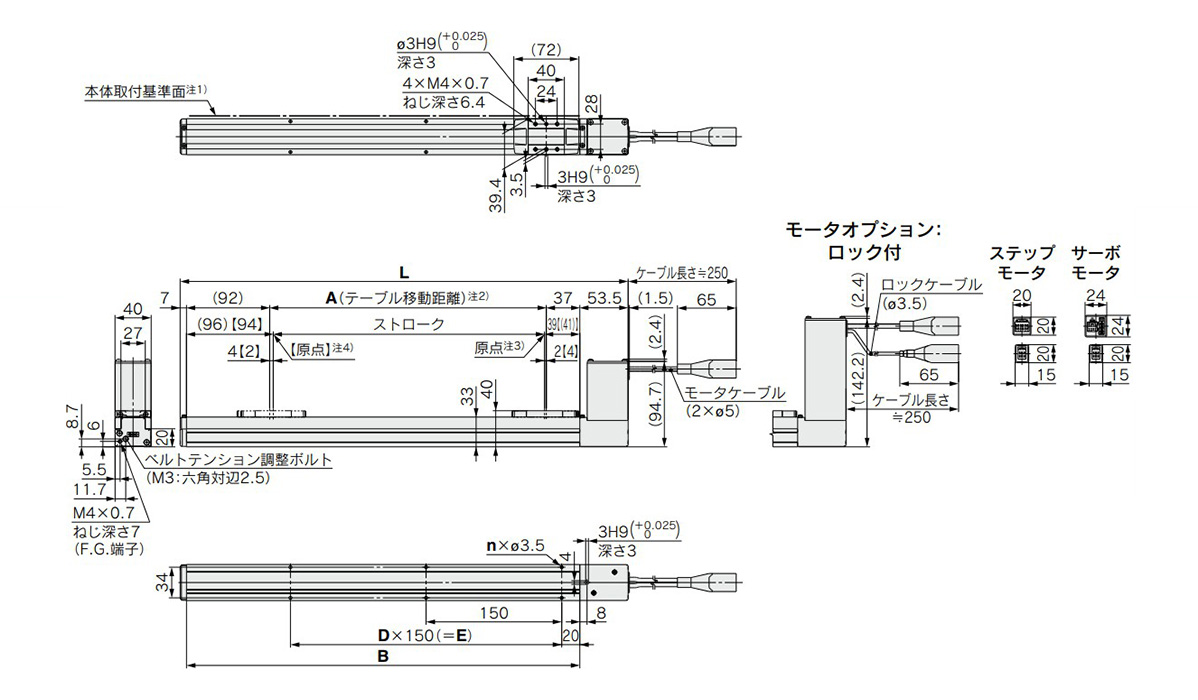
LEFB16 dimensional drawing
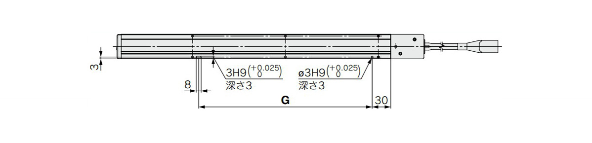
LEFB16 positioning pin hole (Note 5) (Optional): Body bottom surface dimensions
- LEFB16□T-300□/L: 495.5 mm, A: 306 mm, B: 435 mm, n: 6 mm, D: 2 mm, E: 300 mm, G: 280 mm
- LEFB16□T-500□/L: 695.5 mm, A: 506 mm, B: 635 mm, n: 10 mm, D: 4 mm, E: 600 mm, G: 580 mm
- LEFB16□T-600□/L: 795.5 mm, A: 606 mm, B: 735 mm, n: 10 mm, D: 4 mm, E: 600 mm, G: 580 mm
- LEFB16□T-700□/L: 895.5 mm, A: 706 mm, B: 835 mm, n: 12 mm, D: 5 mm, E: 750 mm, G: 730 mm
- LEFB16□T-800□/L: 995.5 mm, A: 806 mm, B: 935 mm, n: 14 mm, D: 6 mm, E: 900 mm, G: 880 mm
- LEFB16□T-900□/L: 1,095.5 mm, A: 906 mm, B: 1,035 mm, n: 14 mm, D: 6 mm, E: 900 mm, G: 880 mm
- LEFB16□T-1000□/L: 1,195.5 mm, A: 1,006 mm, B: 1,135 mm, n: 16 mm, D: 7 mm, E: 1,050 mm, G: 1,030 mm
Note 1: Because of the rounded chamfering, when mounting the actuator using the body mounting reference plane, set the height of the opposite surface or pin to be at least 2 mm or more. (Recommended height: 5 mm)
Note 2: Distance within which the table can move when it returns to origin, etc. Make sure any workpiece mounted on the table does not interfere with the workpieces and equipment, etc., around the table.
Note 3: Position after return to origin.
Note 4: Values within [ ] are for when the direction of return to origin has been changed.
Note 5: When using the body bottom positioning pin holes, do not use the housing B bottom pin hole.
Diagram
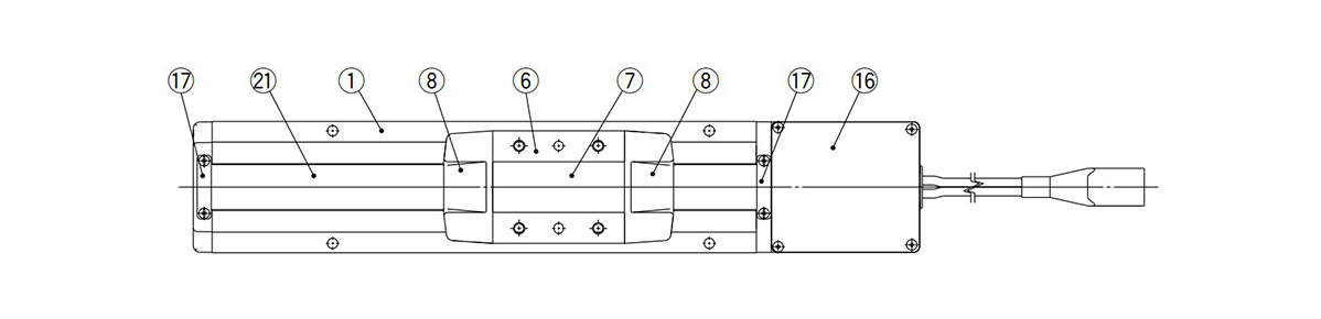
LEFB Series diagram 1
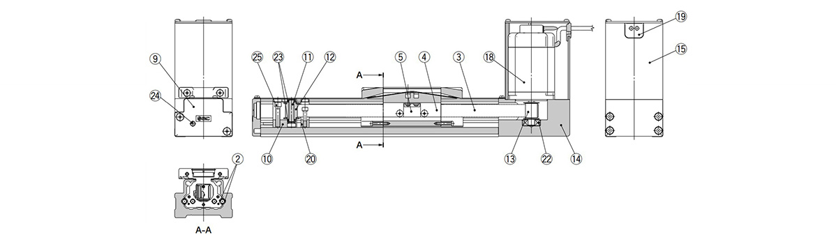
LEFB Series diagram 2
| Number | Part Name | Material | Note |
|---|---|---|---|
| 1 | Body | Aluminum alloy | Anodized |
| 2 | Rail Guide | - | - |
| 3 | Belt | - | - |
| 4 | Belt Holder | Carbon steel | Chromated |
| 5 | Belt Stopper | Aluminum alloy | Anodized |
| 6 | Table | Aluminum alloy | Anodized |
| 7 | Blanking Plate | Aluminum alloy | Anodized |
| 8 | Seal Band Holder | Synthetic resin | - |
| 9 | Housing A | Aluminum diecast | Coating |
| 10 | Pulley Holder | Aluminum alloy | - |
| 11 | Pulley Shaft | Stainless steel | - |
| 12 | End Pulley | Aluminum alloy | Anodized |
| 13 | Motor Pulley | Aluminum alloy | Anodized |
| 14 | Motor Mount | Aluminum alloy | Anodized |
| 15 | Motor Cover | Aluminum alloy | Anodized |
| 16 | End Cover | Aluminum alloy | Anodized |
| 17 | Band Stopper | Stainless steel | - |
| 18 | Motor | - | - |
| 19 | Rubber Bushing | NBR | - |
| 20 | Stopper | Aluminum alloy | - |
| 21 | Dust Seal Band | Stainless steel | - |
| 22 | Bearing | - | - |
| 23 | Bearing | - | - |
| 24 | Tension Adjustment Cap Screw | Chrome molybdenum steel | Chromated |
| 25 | Pulley Retaining Screw | Chrome molybdenum steel | Chromated |
Notes
- *Do not apply load in excess of the specification limits. Select a suitable actuator by work load and allowable moment. If the product is used outside of the specification limits, the unbalanced load applied to the guide will be excessive and have adverse effects, such as creating play on the guide, degrading accuracy and shortening the lifespan of the product.
- *Do not use the product in applications where excessive external force or impact force is applied to it. Doing so can cause the product to malfunction.
- *Refer to the SMC catalog for product information other than what is detailed above.
- *The product image is a representative image only.
Référence pièce
|
|---|
| LEFB16T-300-R11P1 |
| Référence pièce | Relatif à |
Prix unitaire standard
| Quantité minimale de commande | Remise sur volume | Stroke (mm) | Max. Transportable Mass Range (Horizontal) (kg) | Max. Transportable Mass (Horizontal) (kg) | Lead (mm) | I/O Module | Table Width W1 (mm) | Brake | Table Length L1 (mm) | Maximum Velocity (mm/sec) | Taille | Type de moteur | Options de moteur | Type d'actionneur / de câble | Longueur de câble d'actionneur (m) | Type de contrôleur / pilote | Longueur de câble E/S / fiche de communication (m) | Méthode de montage du contrôleur / pilote | Application de graisse (partie de bande d’étanchéité) | Support de montage de commutateur auto | Trou de goupille de positionnement | |
|---|---|---|---|---|---|---|---|---|---|---|---|---|---|---|---|---|---|---|---|---|---|---|---|---|---|
| - | 1,394.23 € | 1 | 26 jours | 300 | 0 à 2.0 | 1 | 48 | PNP | 39.4 | Non fourni | 72 | 3 000 | 16 | Moteur pas à pas (servo 24VDC) | Sans verrouillage | Câble robotique (câble résistant à la flexion) | 1.5 | LECP1 (sans programmation) | 1.5 | Type à montage par vis | - | - | - |
Loading...
Informations de base
| Main Body, Peripheral Components | Corps principal | Type | Glissières | Drive Method | Courroies |
|---|---|---|---|---|---|
| Guide | Fourni | Input Power Supply | 24VDC | Position Detection | Incrémentiel |
| Noise Filters | Non fourni | Environnement de fonctionnement | Standard | Positioning Repeatability(µm) | ±80 |
Vous vous trouvez sur la page de Actionneurs linéaires / Actionneur électrique à curseur avec entraînement par courroie Série LEFB Moteur pas à pas/Servomoteur, le numéro d'article est le suivant: LEFB16T-300-R11P1.
Veuillez trouver plus de détails concernant les particularités et les dimensions sous le numéro d'article LEFB16T-300-R11P1.
Configurer
Propriétés de base
-
Application de graisse (partie de bande d’étanchéité)
- Oui
- Sans (spécifications du rouleau)
-
Support de montage de commutateur auto
- 1 pièce incluse (inclure)
- Sans
-
Trou de goupille de positionnement
- Bas du boîtier B
-
Type
- LEFB
-
Stroke(mm)
-
Max. Transportable Mass Range (Horizontal)(kg)
- 0 à 2.0
- 2,1 à 5,0
- 5,1 à 10,0
- 10,1 à 20,0
-
Max. Transportable Mass (Horizontal)(kg)
-
Lead(mm)
-
I/O Module
- NPN
- PNP
- DeviceNet
- Ethernet
- Non fourni
- EtherCAT
- IO-Link
- PROFINET
-
Table Width W1(mm)
-
Brake
- Non fourni
- Fourni
-
Table Length L1(mm)
-
Maximum Velocity(mm/sec)
-
Taille
- 16
- 25
- 32
-
Type de moteur
- Moteur pas à pas (servo 24VDC)
- Servomoteur (24 V DC)
-
Options de moteur
- Sans verrouillage
- With lock
-
Type d'actionneur / de câble
- Câble robotique (câble résistant à la flexion)
- Câble standard
- Without cable
-
Longueur de câble d'actionneur(m)
- 1.5
- 3
- 5
- 8
- 10
- 15
- 20
- Without cable
-
Type de contrôleur / pilote
- JXCD1 (entrées directes DeviceNet)
- JXCE1 (entrées directes EtherCAT)
- JXCL1 (entrées directes IO-Link)
- JXCP1 (entrées directes PROFINET)
- LECP1 (sans programmation)
- LECA6 (entrées de positionnement)
- LECP6/LECA6 (type d'entrée de données de pas)
- LECP6/LECA6, PNP, step data input type
- JXC91 (entrées directes EtherNet/IP)
- LECPA (entrées impulsionnelles)
- Sans
-
Longueur de câble E/S / fiche de communication(m)
- 1.5
- 3
- 5
- Sans connecteur
- Sans câble (sans connecteur de communication)
-
Méthode de montage du contrôleur / pilote
- Type de montage sur rail DIN
- Type à montage par vis
-
Filtrer par type de données CAO
- 2D
- 3D
Filtrer par jours d'expédition standard
-
- Tous les articles
- 4 jours ou moins
- 21 jours ou moins
- 26 jours ou moins
- 98 jours ou moins
Propriétés optionnelles
- Les spécifications et les dimensions de certaines pièces peuvent ne pas être intégralement indiquées. Pour plus de détails, reportez-vous aux catalogues des fabricants .
Variantes de ce produit
| Référence pièce |
|---|
| LEFB16AT-1000-R56P5D |
| LEFB16AT-1000B-R36N3D |
| LEFB16AT-1000B-R56P1D |
| LEFB16T-300-R3 |
| LEFB16T-300-R31P1 |
| LEFB16T-300-R31P3 |
| Référence pièce | Relatif à | Prix unitaire standard | Quantité minimale de commande | Remise sur volume | Jour d'expédition standard ? | Stroke (mm) | Max. Transportable Mass Range (Horizontal) (kg) | Max. Transportable Mass (Horizontal) (kg) | Lead (mm) | I/O Module | Table Width W1 (mm) | Brake | Table Length L1 (mm) | Maximum Velocity (mm/sec) | Taille | Type de moteur | Options de moteur | Type d'actionneur / de câble | Longueur de câble d'actionneur (m) | Type de contrôleur / pilote | Longueur de câble E/S / fiche de communication (m) | Méthode de montage du contrôleur / pilote | Application de graisse (partie de bande d’étanchéité) | Support de montage de commutateur auto | Trou de goupille de positionnement |
|---|---|---|---|---|---|---|---|---|---|---|---|---|---|---|---|---|---|---|---|---|---|---|---|---|---|
| - | 1,943.54 € | 1 | 26 jours | 1,000 | 0 à 2.0 | 1 | 48 | PNP | 39.4 | Non fourni | 72 | 3 000 | 16 | Servomoteur (24 V DC) | Sans verrouillage | Câble robotique (câble résistant à la flexion) | 5 | LECP6/LECA6, PNP, step data input type | 5 | Type de montage sur rail DIN | - | - | - | ||
| - | 2,148.96 € | 1 | 26 jours | 1,000 | 0 à 2.0 | 1 | 48 | NPN | 39.4 | Non fourni | 72 | 3 000 | 16 | Servomoteur (24 V DC) | With lock | Câble robotique (câble résistant à la flexion) | 3 | LECP6/LECA6, PNP, step data input type | 3 | Type de montage sur rail DIN | - | - | - | ||
| - | 2,221.83 € | 1 | 26 jours | 1,000 | 0 à 2.0 | 1 | 48 | PNP | 39.4 | Non fourni | 72 | 3 000 | 16 | Servomoteur (24 V DC) | With lock | Câble robotique (câble résistant à la flexion) | 5 | LECP6/LECA6, PNP, step data input type | 1.5 | Type de montage sur rail DIN | - | - | - | ||
| - | 1,067.80 € | 1 | 26 jours | 300 | 0 à 2.0 | 1 | 48 | Non fourni | 39.4 | Non fourni | 72 | 3 000 | 16 | Moteur pas à pas (servo 24VDC) | Sans verrouillage | Câble robotique (câble résistant à la flexion) | 3 | Sans | Sans câble (sans connecteur de communication) | Type à montage par vis | - | - | - | ||
| - | 1,430.33 € | 1 | 26 jours | 300 | 0 à 2.0 | 1 | 48 | PNP | 39.4 | Non fourni | 72 | 3 000 | 16 | Moteur pas à pas (servo 24VDC) | Sans verrouillage | Câble robotique (câble résistant à la flexion) | 3 | LECP1 (sans programmation) | 1.5 | Type à montage par vis | - | - | - | ||
| - | 1,436.63 € | 1 | 26 jours | 300 | 0 à 2.0 | 1 | 48 | PNP | 39.4 | Non fourni | 72 | 3 000 | 16 | Moteur pas à pas (servo 24VDC) | Sans verrouillage | Câble robotique (câble résistant à la flexion) | 3 | LECP1 (sans programmation) | 3 | Type à montage par vis | - | - | - |
Assistance technique
Mode de paiement


Fabrication à la demande
Certificats


Copyright © MISUMI Corporation All Rights Reserved.