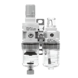
AC10A-40A-A (FRL), Nouveau modèle modulaire, filtre régulateur + lubrificateur

[Features]
· The inside can be seen from all angles (360°).
· The bowl is protected from the external environment, ensuring high levels of safety.
(i)Remarque
- Les produits présentés dans l'image sont représentatifs. Les données CAO ne sont pas prises en charge pour certains numéros de modèle.
Référence pièce
Vous pouvez trouver ici le numéro
de référence lié au produit recherché.
Air Combination Filter Regulator + Lubricator, AC10A-A To AC40A-A Specifications
Model Number Notation

Model number notation: images
| - | Code | Contents | (1) | ||||||
|---|---|---|---|---|---|---|---|---|---|
| Body size | |||||||||
| 10 | 20 | 30 | 40 | ||||||
| (2) | Screw Type | No symbol | Metric thread (M5) | ● | - | - | - | ||
| Rc | - | ● | ● | ● | |||||
| N Note 1) | NPT | - | ● | ● | ● | ||||
| F Note 2) | G | - | ● | ● | ● | ||||
| (3) | Piping connection port diameter | M5 | M5 | ● | - | - | - | ||
| 01 | 1/8 | - | ● | - | - | ||||
| 02 | 1/4 | - | ● | ● | ● | ||||
| 03 | 3/8 | - | - | ● | ● | ||||
| 04 | 1/2 | - | - | - | ● | ||||
| 06 | 3/4 | - | - | - | ● | ||||
| (4) | Note 3) Option | a | Float type auto drain | No symbol | Without auto drain | ● | ● | ● | ● |
| C Note 4) | N.C. (Normally Closed) Drain port is closed when no pressure is applied | ● | ● | ● | ● | ||||
| D Note 5) | N.O. (Normally Open) Drain port is open when no pressure is applied | - | - | ● | ● | ||||
| b | Pressure gauge Note 6) | No symbol | Without pressure gauge | ● | ● | ● | ● | ||
| G | Round-type pressure gauge (without limit indicator) | ● | - | - | - | ||||
| Round-type pressure gauge (with limit indicator) | - | ● | ● | ● | |||||
| M | Round-type pressure gauge (with color zone) | - | ● | ● | ● | ||||
| (5) | Attachment | c | Check valve | No symbol | No attachment | ● | ● | ● | ● |
| K | Mounting position: AW + K + AL | - | ● | ● | ● Note 7) | ||||
| d | Pressure switch | No symbol | No attachment | ● | ● | ● | ● | ||
| S Note 8) | Mounting position: AW + S + AL | - | ● | ● | ● | ||||
| e | Residual pressure relief 3-port valve | No symbol | No attachment | ● | ● | ● | ● | ||
| V | Mounting position: AW + AL + V | - | ● | ● | ● | ||||
| (6) | Semi-standard | f | Set pressure Note 9) | No symbol | 0.05 to 0.7‑MPa setting | ● | ● | ● | ● |
| 1 | 0.02 to 0.2‑MPa setting | ● | ● | ● | ● | ||||
| g | Bowl Note 10) | No symbol | Polycarbonate bowl | ● | ● | ● | ● | ||
| 2 | Metal bowl | ● | ● | ● | ● | ||||
| 6 | Nylon bowl | ● | ● | ● | ● | ||||
| 8 | Metal bowl with level gauge | - | - | ● | ● | ||||
| C | With bowl guard | - | ● | -Note 11) | -Note 11) | ||||
| 6C | With bowl guard (nylon bowl) | - | ● | -Note 12) | -Note 12) | ||||
| h | Filter Note 13) Regulator Drain exhaust outlet | No symbol | With drain cock | ● | ● | ● | ● | ||
| J Note 14) | Drain guide 1/8 | - | ● | - | - | ||||
| Drain guide 1/4 | - | - | ● | ● | |||||
| W Note 15) | Drain cock with barb fitting (ø6 [diameter 6 mm] ×; ø4 [diameter 4 mm] for nylon tubes) | - | - | ● | ● | ||||
| (6) | Semi-standard | i | Lubricator Oil discharge outlet | No symbol | Without drain cock | ● | ● | ● | ● |
| 3Note 16) | Lubricator with drain cock | ● | ● | ● | ● | ||||
| j | Exhaust mechanism | No symbol | Relieving type | ● | ● | ● | ● | ||
| N | Non-relieving type | ● | ● | ● | ● | ||||
| k | Flow direction | No symbol | Flow direction: left → right | ● | ● | ● | ● | ||
| R | Flow direction: right → left | ● | ● | ● | ● | ||||
| l | Pressure unit | No symbol | Unit used on nameplate and pressure gauge: MPa | ● | ● | ● | ● | ||
| Z Note 17) | Name plate, bowl caution plate and pressure gauge units: psi, °F | ○ Note 18) | ○ Note 18) | ○ Note 18) | ○ Note 18) | ||||
Note 1) Drain guide is NPT 1/8 (applicable to the AC20A-A); and NPT1/4 (applicable to the AC30A-A to AC40A-A).
The auto drain port comes with ø3/8" one-touch fitting (applicable to the AC30A-A to AC40A-A).
Note 2) The drain guide is G1/8 (applicable to the AC20A-A); and G1/4 (applicable to the AC30A-A to AC40A-A).
Note 3) Options G and M are not assembled and are supplied loose at the time of shipment.
Note 4) When pressure is not applied, condensate which does not start the auto drain mechanism will remain in the drain bowl. Therefore manual release before ending operations is recommended.
Note 5) If the compressor used is small (0.75 kW, discharge flow rate is less than 100 L/min [ANR]), air leakage from the drain cock may occur when operations start. As such an N.C. type is recommended.
Note 6) When the pressure gauge is attached, a 1.0 MPa will be fitted for standard (0.7 MPa setting) type; 0.4 MPa for the 0.2‑MPa type (1.0‑MPa pressure gauge only for the AC10A-A).
Note 7) Not available with piping connection port size: 06.
Note 8) The bracket position varies depending on the pressure switch mounting.
Note 9) Pressure can be set higher than the specification pressure in some cases, but use with the pressure within the specified range.
Note 10) A bowl guard is provided as standard (polycarbonate).
Note 11) A bowl guard is provided as standard (nylon).
Note 12) Float type auto drain: Cannot be selected in combination with C, D.
Note 13) Does not include a valve function.
Note 14) Metal bowl: Cannot be selected in combination with 2, 8.
Note 15) When choosing with W (filter regulator drain port): the drain cock of the lubricator will be with barb fittings.
Note 16) Thread type: M5, NPT. Under new Japanese measurement laws, this product is only available for sale outside of Japan (SI units are used in Japan).
However, the pressure switch offers dual unit presentation in both MPa and psi.
Round-type pressure gauge (with color zone): cannot be used in combination with M.
Note 17) ○ is for thread types M5 and NPT only.
Standard specification
| Model | AC10A-A | AC20A-A | AC30A-A | AC40A-A | AC40A-06-A | |
|---|---|---|---|---|---|---|
| Components | Filter regulator [AW] | AW10-A | AW20-A | AW30-A | AW40-A | AW40-06-A |
| Lubricator [AL] | AL10-A | AL20-A | AL30-A | AL40-A | AL40-06-A | |
| Piping connection port diameter | M5 ×; 0.8 | 1/8, 1/4 | 1/4, 3/8 | 1/4, 3/8, 1/2 | 3/4 | |
| Pressure gauge connection port size [AW] | 1/16 | 1/8 | ||||
| Applicable fluids | Air | |||||
| Ambient temperature and working fluid temperature | −5 to 60°C (no freezing) | |||||
| Proof pressure | 1.5 MPa | |||||
| Maximum operating pressure | 1.0 MPa | |||||
| Set pressure range [AW] | 0.05 to 0.7 MPa | |||||
| Filtration [AW] | 5 mm | |||||
| Recommended lubricant [AL] | Type 1 turbine oil (ISO VG32) | |||||
| Case materials [AW/AL] | Polycarbonate | |||||
| Case guard [AW/AL] | - | Semi-standard (steel) | Standard equipment (polycarbonate) | |||
| Structure [AW] | Relieving type | |||||
| Weight (kg) | 0.20 | 0.34 | 0.67 | 1.24 | 1.35 | |
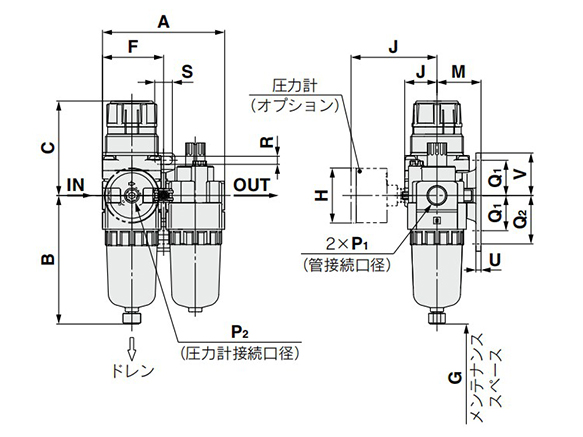
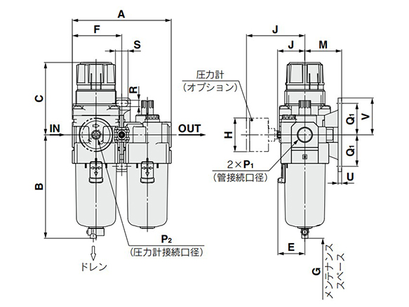
Air Combination Filter Regulator + Lubricator, AC10A-A To AC40A-A Dimensions
(Unit: mm)

AC10A-A/AC20A-A dimensional drawing
(Unit: mm)

AC30A-A to AC40A-06-A dimensional drawing
| Model | Standard specification | |||||||||||||||
|---|---|---|---|---|---|---|---|---|---|---|---|---|---|---|---|---|
| P 1 | P 2 | A | B | C Note) | E | F | G | J | Bracket mounting dimensions | |||||||
| M | Q 1 | Q 2 | R | S | U | V | ||||||||||
| AC10A-A | M5 ×; 0.8 | 1/16 | 56 | 59.9 | 47.4 | - | 28 | 25 | 12.5 | 25 | 20 | 27 | 4.5 | 6.8 | 3 | 24.5 |
| AC20A-A | 1/8, 1/4 | 1/8 | 83.2 | 87.6 | 67.4 | - | 41.6 | 60 | 23.4 | 30 | 24 | 33 | 5.5 | 12 | 3.5 | 29 |
| AC30A-A | 1/4, 3/8 | 1/8 | 110.2 | 115.1 | 83.5 | 30 | 55.1 | 80 | 30.5 | 41 | 35 | - | 7 | 14 | 4 | 41 |
| AC40A-A | 1/4, 3/8, 1/2 | 1/8 | 145.2 | 147.1 | 100 | 38.4 | 72.6 | 110 | 36.1 | 50 | 40 | - | 9 | 18 | 5 | 48 |
| AC40A-06-A | 3/4 | 1/8 | 155.2 | 149.1 | 101.5 | 38.4 | 77.6 | 110 | 39.6 | 50 | 40 | - | 9 | 18 | 5 | 48 |
| Model | Option specification | Semi-standard specifications | |||||||||
|---|---|---|---|---|---|---|---|---|---|---|---|
| Round-type pressure gauge | Round-type pressure gauge (with color zone) | With auto drain | With barb fittings | With drain guide | Metal bowl | Metal bowl with drain guide | Metal bowl with level gauge | Metal bowl with level gauge with drain guide | |||
| H | J | H | J | B | B | B | B | B | B | B | |
| AC10A-A | ø26 (diameter 26 mm) | 26 | - | - | 77.9 | - | - | 59.3 | - | - | - |
| AC20A-A | ø37.5 (diameter 37.5 mm) | 58.5 | ø37.5 (diameter 37.5 mm) | 59.5 | 104.9 | - | 91.4 | 87.4 | 93.9 | - | - |
| AC30A-A | ø37.5 (diameter 37.5 mm) | 65 | ø37.5 (diameter 37.5 mm) | 66 | 156.8 | 123.6 | 121.9 | 117.6 | 122.1 | 137.6 | 142.1 |
| AC40A-A | ø42.5 (diameter 42.5 mm) | 72 | ø42.5 (diameter 42.5 mm) | 72 | 186.9 | 155.6 | 153.9 | 149.6 | 154.1 | 169.6 | 174.1 |
| AC40A-06-A | ø42.5 (diameter 42.5 mm) | 72 | ø42.5 (diameter 42.5 mm) | 72 | 188.9 | 157.6 | 155.9 | 151.6 | 156.1 | 171.6 | 176.1 |
Note) The dimension C is the length when the filter regulator knob (handle) is unlocked.
Référence pièce
|
|---|
| AC40A-N06-A |
| AC40A-N06-Z-A |
| AC40A-N06DG-3Z-A |
| AC40A-N06G-Z-A |
| Référence pièce |
Prix unitaire standard
| Quantité minimale de commande | Remise sur volume | Diamètre de raccordement | Matériaux du boîtier | Protection de cuve | Mécanisme d'échappement | Sens du débit | Robinet de purge | Jauge de pression | Size of Body | Check Valve | Pressure Switch | Residual Pressure Relief 3-Port Connection Valve | Set Pressure | Drain Outlet | Lubricator Oil Discharge Outlet | Pressure Unit | |
|---|---|---|---|---|---|---|---|---|---|---|---|---|---|---|---|---|---|---|---|
123.63 € | 1 | 26 jours | NPT3/4 | [Résine] Boîtier en polycarbonate | Disponible | Type de relief | [Débit standard (de gauche à droite)] Sens du débit | [Manuel] Manuel | Non (sans prise de pression) | 40 | Aucun | Aucun | Aucun | 0.05 à 0.7MPa | Avec robinet de vidange | Sans robinet de vidange | Unité utilisée sur la plaque signalétique et la jauge de pression : MPa | ||
123.63 € | 1 | 26 jours | NPT3/4 | [Résine] Boîtier en polycarbonate | Disponible | Type de relief | [Débit standard (de gauche à droite)] Sens du débit | [Manuel] Manuel | Non (sans prise de pression) | 40 | Aucun | Aucun | Aucun | 0.05 à 0.7MPa | Avec robinet de vidange | Sans robinet de vidange | Unités de plaque signalétique, de plaque d'avertissement et de jauge de pression : psi, °F | ||
164.11 € | 1 | 26 jours | NPT3/4 | [Résine] Boîtier en polycarbonate | Disponible | Type de relief | [Débit standard (de gauche à droite)] Sens du débit | [Automatique / manuel] N.O. (Normalement ouvert) à des émissions non pressurisées sans vidange | [Avec jauge de pression standard] Manomètre de forme ronde (avec indicateur de limite) | 40 | Aucun | Aucun | Aucun | 0.05 à 0.7MPa | Avec robinet de vidange | Appareil de lubrification avec robinet de vidange | Unités de plaque signalétique, de plaque d'avertissement et de jauge de pression : psi, °F | ||
133.94 € | 1 | 26 jours | NPT3/4 | [Résine] Boîtier en polycarbonate | Disponible | Type de relief | [Débit standard (de gauche à droite)] Sens du débit | [Manuel] Manuel | [Avec jauge de pression standard] Manomètre de forme ronde (avec indicateur de limite) | 40 | Aucun | Aucun | Aucun | 0.05 à 0.7MPa | Avec robinet de vidange | Sans robinet de vidange | Unités de plaque signalétique, de plaque d'avertissement et de jauge de pression : psi, °F |
Loading...
Informations de base
| Unité combinée de régulateur | Régulateur de filtre + lubrificateur | Filtre, niveau de filtration | 5μm | Qualité de l'air comprimé | Air sec de qualité générale |
|---|---|---|---|---|---|
| Pression de service max.(MPa) | 1 |
Configurer
Propriétés de base
-
Matériaux du boîtier
- Résine
- Résine
-
Protection de cuve
- NA
- Disponible
-
Mécanisme d'échappement
- Type sans relief
- Type de relief
-
Sens du débit
- Débit standard (de gauche à droite)
- Débit inversé (de droite à gauche)
- Débit standard (de gauche à droite)
-
Robinet de purge
- Manuel
- Automatique / manuel
- Non fourni
- Manuel
-
Jauge de pression
- Non (sans prise de pression)
- Avec jauge de pression standard
-
Size of Body
-
Check Valve
- Aucun
- Oui
-
Pressure Switch
- Aucun
- Oui
-
Residual Pressure Relief 3-Port Connection Valve
- Aucun
- Oui
-
Set Pressure
- 0.02 à 0.2MPa
- 0.05 à 0.7MPa
-
Drain Outlet
- Guide de vidange 1/4
- Guide de vidange 1/8
- Avec robinet de vidange, raccord cannelé (pour tube nylon ⌀6 × ⌀4)
- Avec robinet de vidange
-
Lubricator Oil Discharge Outlet
- Appareil de lubrification avec robinet de vidange
- Sans robinet de vidange
-
Pressure Unit
- Unité utilisée sur la plaque signalétique et la jauge de pression : MPa
- Unités de plaque signalétique, de plaque d'avertissement et de jauge de pression : psi, °F
-
Type
- AC10A
- AC20A
- AC30A
- AC40A
-
Diamètre de raccordement
- Rc1/8
- Rc1/4
- Rc3/8
- Rc1/2
- Rc3/4
- NPT1/4
- NPT3/8
- G1/4
- G3/8
- NPT1/2
- NPT3/4
- NPT1 / 8
- G1 / 8
- G1/2
- G3/4
- M5
-
Filtrer par type de données CAO
- 2D
- 3D
Filtrer par jours d'expédition standard
-
- Tous les articles
- 4 jours ou moins
- 6 jours ou moins
- 26 jours ou moins
Propriétés optionnelles
- Les spécifications et les dimensions de certaines pièces peuvent ne pas être intégralement indiquées. Pour plus de détails, reportez-vous aux catalogues des fabricants .


