Électrovannes 5 voies / métriques / pilotées, étanchéité métallique, VFS3000
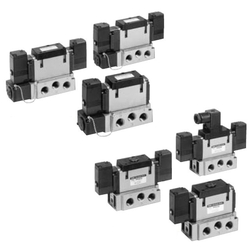
[Features]
· Large valve capacity 3/8: C: 5.8 dm3/(s·bar)
· Low power consumption: 1.8 W DC
· Easy maintenance and inspection
· 2 types of subplate, plug-in type and non-plug-in type.
(i)Remarque
- Les images des produits peuvent être représentatives. Reportez-vous au catalogue du fabricant pour plus de détails.
Référence pièce
Vous pouvez trouver ici le numéro
de référence lié au produit recherché.
Metal Seal, 5-Port Pilot Type, Plug-In Type / Non-Plug-In Type VFS3000 Series Specifications
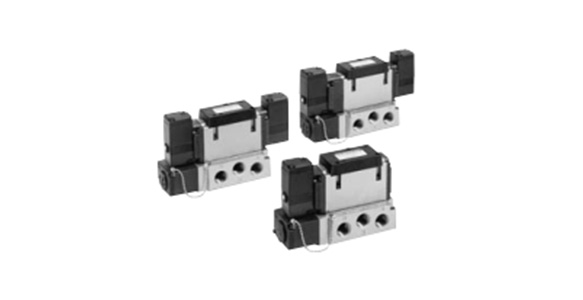
VFS3000 Series plug-in type external appearance
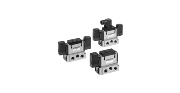
VFS3000 Series non-plug-in type external appearance
| Valve Specifications | Fluid | Air | ||
|---|---|---|---|---|
| Maximum Operating Pressure | 1.0 MPa | |||
| Minimum Operating Pressure | 0.1 MPa | |||
| Guaranteed Proof Pressure | 1.5 MPa | |||
| Ambient Temperature and Operating Fluid Temperature | *1 -10 to 60°C | |||
| Lubrication | *2 Not required | |||
| Pilot Valve – Manual Operation | Non-locking push type (flush) | |||
| Impact Resistance / Vibration Resistance | *3 150/50 m/s2 | |||
| Enclosure | *4 Type E: dust-proof (IP50 equivalent), Type F: drip-proof (IP52 equivalent) *5, Type D: splash-proof (IP54 equivalent) *6 | |||
| Electrical Specifications | Coil Rated Voltage | 100 V, 200 V AC (50/60 Hz), 24 V DC | ||
| Allowable Voltage Fluctuation | -15% to +10% of rated voltage | |||
| Coil Insulation Type | *5 Class B or equivalent (130°C) | |||
| Apparent Power (Power Consumption) AC | Starting | 5.6 VA / 50 Hz, 5.0 VA / 60 Hz | ||
| Holding | 3.4 VA (2.1 W) / 50 Hz, 2.3 VA (1.5 W) / 60 Hz | |||
| Current Consumption DC | 1.8 W (2.04 W: with light and surge voltage suppressor) | |||
| Electrical Entry | Plug-in type | Conduit terminal | ||
| Non-plug-in type | DIN terminal, grommet terminal | |||
*1: Use dry air when at low temperatures.
*2: If lubricating, use turbine oil class 1 (ISO VG32).
*3: Impact resistance: No malfunctions after testing using a drop-type impact tester under the following conditions: in the axial direction and at a right angle to the main valve and armature in both energized and non-energized states (once for each condition state). (Initial value)
Vibration resistance: No malfunctions occurred in a 1-sweep test between 45 and 2,000 Hz. The test was performed in both energized and non-energized states and in the axial direction and at right angles to the main valve and armature. (Initial value)
*4: Based on JlS C 0920.
*1: Based on JIS C 4003.
*6: Type F and Type D protective structures indicate no light or surge voltage suppressor. Those with a light and surge voltage suppressor are type F (IP50 equivalent) and type D: (IP50 equivalent).
| Pilot Method | *External pilot type | |
|---|---|---|
| Manual Operation | Main Valve | Direct manual method |
| Pilot Valve | Non-locking push type (extended), locking type (tool required), locking type (lever) | |
| Coil Rated Voltage | 110 to 120 V, 220 V, 240 V AC (50/60 Hz) | |
| 12 V, 100 V DC | ||
| Piping Specifications | Bottom piping type | |
| Options | With light and surge voltage suppressor | |
*Operating pressure: 0 to 1 MPa / Pilot pressure: 0.1 to 1 MPa
Model
| Configuration | Model | Piping connection port diameter Rc | Flow Rate Characteristics | *1: Maximum Operating Frequency CPM | *2: Response Time ms | *3: Weight kg | |||||||
|---|---|---|---|---|---|---|---|---|---|---|---|---|---|
| Plug-In | Non-Plug-In | 1 → 4/2 (P → A/B) | 4/2 → 5/3 (A/B → R1/R2) | ||||||||||
| C (dm3/(s·bar)) | b | Cv | C (dm3/(s·bar)) | b | Cv | ||||||||
| 2 Position | Single | VFS3100 | VFS3110 | 1/4 | 6.0 | 0.15 | 1.4 | 5.8 | 0.12 | 1.3 | 1,200 | 20 or less | 0.31 |
| 3/8 | 7.3 | 0.23 | 1.8 | 6.8 | 0.12 | 1.6 | |||||||
| Double | VFS3200 | VFS3210 | 1/4 | 6.0 | 0.15 | 1.4 | 5.8 | 0.12 | 1.3 | 1,500 | 15 or less | 0.41 | |
| 3/8 | 7.3 | 0.23 | 1.8 | 6.8 | 0.12 | 1.6 | |||||||
| 3 Position | Closed Center | VFS3300 | VFS3310 | 1/4 | 5.8 | 0.21 | 1.4 | 5.4 | 0.14 | 1.2 | 600 | 40 or less | 0.43 |
| 3/8 | 6.8 | 0.22 | 1.7 | 6.3 | 0.12 | 1.5 | |||||||
| Exhaust Center | VFS3400 | VFS3410 | 1/4 | 6.1 | 0.23 | 1.4 | 5.0 | 0.14 | 1.2 | 600 | 40 or less | 0.43 | |
| 3/8 | 7.4 | 0.20 | 1.8 | 5.6 | 0.18 | 1.3 | |||||||
| Pressure Center | VFS3500 | VFS3510 | 1/4 | 6.0 | 0.22 | 1.5 | 5.8 | 0.16 | 1.3 | 600 | 40 or less | 0.43 | |
| 3/8 | 7.2 | 0.19 | 1.8 | 7.1 | 0.18 | 1.8 | |||||||
| Perfect | VFS3600 | VFS3610 | 1/4 | 4.0 | - | - | 3.5 | - | - | 600 | 50 or less | 0.91 | |
| 3/8 | 4.0 | - | - | 3.7 | - | - | |||||||
*1: The minimum operating frequency is according to JIS B 8419:2010 (once per 30 days).
*2: According to JIS B 8419:2010 (value with supply pressure of 0.5 MPa).
*3: Add values to the table as follows: For no sub-plate and for plug-in sub-plate, add 0.30 kg. For non-plug-in sub-plate, add 0.27 kg.
*4: *1 and *2 assume controlled clean air.
Product Drawing
Plug-in type / 2-position single, 3-position closed center, exhaust center, pressure center, perfect
(Unit: mm)
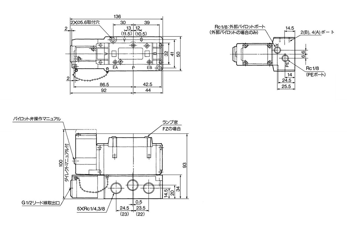
2-position single: VFS3100-□F(Z) dimensional drawing
(Unit: mm)

2-position single: VFS3100-□F(Z) with bottom piping, dimensional drawing
*Values in ( ) are for Rc 1/4
(Unit: mm)
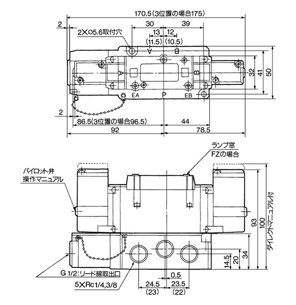
2-position double: VFS3200-□F(Z), 3-position closed center: VFS3300-□F(Z), 3-position exhaust center: VFS3400-□F(Z), 3-position pressure center: VFS3500-□F(Z) dimensional drawing
*Values in ( ) are for Rc 1/4
(Unit: mm)
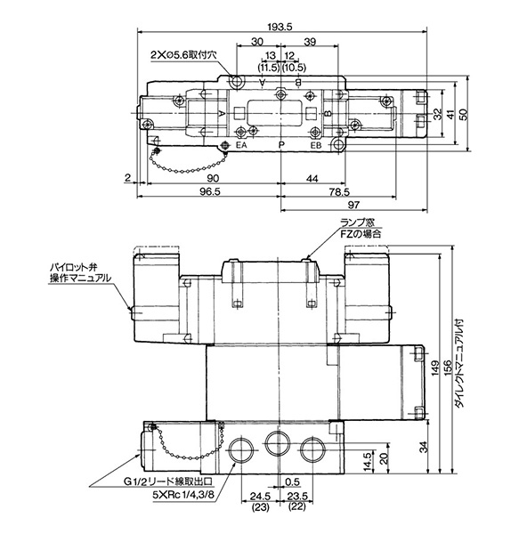
3-position perfect: VFS3600-□F (Z) dimensional drawing
*Values in ( ) are for Rc 1/4
Product Structure Drawing
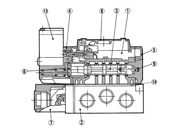
2 position single structure drawing
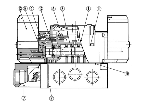
2-position double structure drawing
| Number | Part name | Material |
|---|---|---|
| 1 | Body | Die-cast aluminum |
| 2 | Sub-plate | Die-cast aluminum |
| 3 | Spool/Sleeve | Stainless steel |
| 4 | Adapter Plate | Resin |
| 5 | End Plate | Resin |
| 6 | Piston | Resin |
| 7 | Junction Cover | Resin |
| 8 | Light Cover | Resin |
| 9 | Return Spring | Stainless steel |
| 10 | Gasket | HNBR |
| 11 | Hexagon Socket Head Bolt | Steel |
| 12 | Detent Assembly | - |
| 13 | Pilot Valve Assembly | - |
*See p. 941 in the SMC catalog for details on ordering pilot valve assemblies.
Product JIS Symbol
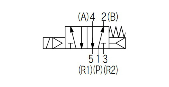
JIS symbol for 2 position single
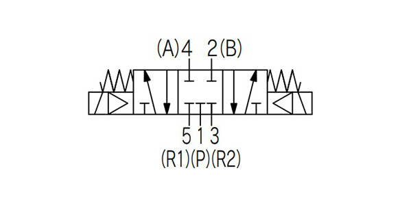
JIS symbol for 3 position closed center
Precautions
- Be sure to read the individual product cautions before use.
- See the SMC catalog for product information other than that detailed above.
Référence pièce
|
|---|
| VFS3110-2D-Q |
| VFS3210-2DO-Q |
| Référence pièce |
Prix unitaire standard
| Quantité minimale de commande | Remise sur volume | Type | Application | Nombre de ports | Sens du montage | Caractéristiques | Nombre de solénoïdes | Type à commutation | État à la mise hors tension | Tension | Type à port de tuyau | Filetage nominal de tuyauterie | Diam. du cylindre applicable (Ø) | Tuyauterie | Type d'entraînement | Valeur CV | Type de joint | Pression nominale (MPa) | Alimentation en air piloté | Interrupteur manuel | Entrée électrique du fil de sortie | Manuel | Témoin / Suppresseur de surtension | Conformité CE | Type de corps | Spécifications de tuyauterie | Options de corps | Related component type | |
|---|---|---|---|---|---|---|---|---|---|---|---|---|---|---|---|---|---|---|---|---|---|---|---|---|---|---|---|---|---|---|---|
139.69 € | 1 | 26 jours | Électrovannes | Unité de montage du collecteur | Vanne à 5 ports | Base de collecteur | Sans lubrification / Faible courant | [Simple] Simple | Échappement à 2 positions | Reprise automatique (retour de ressort) | 200VAC | - | - | - | Tuyauterie de fondation | Tiroir type piloté | - | Standard | 0,1 à 1,0 | Interne | Non bloquant | Borne DIN | Type non verrouillable par poussoir (aligné) | Aucun | Produit conforme CE | Embase non enfichable | - | Standard | - | ||
187.15 € | 1 | 26 jours | Électrovannes | Unité de montage du collecteur | Vanne à 5 ports | Base de collecteur | Standard / Sans lubrification / Faible courant | Double | Échappement à 2 positions | À retenue automatique | 200VAC | - | - | - | Tuyauterie de fondation | Tiroir type piloté | - | Standard | 0,1 à 1,0 | Interne | Non bloquant | Borne DIN sans connecteur | Type non verrouillable par poussoir (aligné) | Aucun | Oui | Embase non enfichable | Port latéral | Standard | - |
Loading...
Configurer
Propriétés de base
-
Type
- Électrovannes
- Composants associés
-
Application
- Utilisation unique
- Unité de montage du collecteur
-
Nombre de ports
- Vanne à 5 ports
-
Sens du montage
- Direct
- Base de collecteur
-
Caractéristiques
- Standard
- Sans lubrification
- Faible courant
-
Nombre de solénoïdes
- Simple
- Double
- Simple
-
Type à commutation
- Échappement à 2 positions
- 3 positions, centre fermé
- Centre d'échappement à 3 positions
- Centre de pression à 3 positions
- Autres
-
État à la mise hors tension
- À retenue automatique
- Reprise automatique (retour de ressort)
-
Type à port de tuyau
- Rc (R)
- NPTF
- G
- Rc (R)
-
Filetage nominal de tuyauterie
-
Diam. du cylindre applicable(Ø)
-
Tuyauterie
- Tuyauterie de fondation
-
Type d'entraînement
- Tiroir type piloté
-
Valeur CV
-
Type de joint
- Standard
-
Pression nominale(MPa)
- 0,1 à 1,0
-
Alimentation en air piloté
- Interne
- Externe
-
Interrupteur manuel
- Non bloquant
- Verrou
-
Entrée électrique du fil de sortie
- Borne DIN
- Borne DIN sans connecteur
- Borne de conduit enfichable
- Borne à passe-fil
-
Manuel
- Type de verrouillage (levier)
- Type de verrouillage (outil requis)
- Type non verrouillable par poussoir (aligné)
- Type à poussoir non verrouillable (type prolongé)
-
Témoin / Suppresseur de surtension
- Aucun
- Avec témoin et suppresseur de surtension
-
Conformité CE
- Oui
- Produit conforme CE
-
Type de corps
- Embase enfichable
- Embase non enfichable
-
Spécifications de tuyauterie
- Port latéral
-
Options de corps
- Manuel direct
- Standard
-
Related component type
- Montage, démontage de soupape pilote
-
Type
- SF4
- VFS3□0□
- VFS3□1□
-
Tension
- 24VDC
- 100VAC
- 200VAC
- 220VAC
- 110/120VAC
- 240VAC
-
Filtrer par type de données CAO
- 2D
- 3D
Filtrer par jours d'expédition standard
-
- Tous les articles
- 4 jours ou moins
- 22 jours ou moins
- 26 jours ou moins
- 98 jours ou moins
Propriétés optionnelles
- Les spécifications et les dimensions de certaines pièces peuvent ne pas être intégralement indiquées. Pour plus de détails, reportez-vous aux catalogues des fabricants .


