VT317, Distributeur 3 / 2 à clapet à commande directe, Tous modèles (Numéros de référence - Téléchargement CAO)

[Features]
· Compact yet with a large valve capacity
· Suitable for use in vacuum applications
· 6 valve functions in 1 valve
(i)Remarque
- Les images des produits peuvent être représentatives. Reportez-vous au catalogue du fabricant pour plus de détails.
Référence pièce
Vous pouvez trouver ici le numéro
de référence lié au produit recherché.
3-Port Solenoid Valve, Direct Operated Poppet Type, Rubber Seal, VT317 Series Specifications
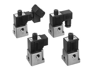
VT317 Series, rubber seal external appearance
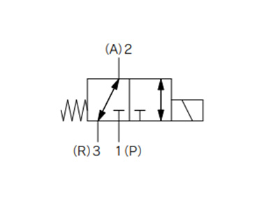
VT317 Series Rubber Seal JIS symbol
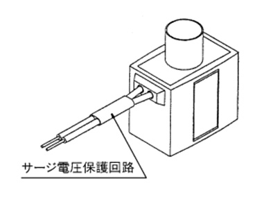
Surge voltage suppressor mounting part (for G)
| Switching Method | Direct operation type 2-position single solenoid | ||
|---|---|---|---|
| Usable Fluids | Air | ||
| Operating Pressure Range | 0 to 0.9 MPa | ||
| Ambient Temperature and Operating Fluid Temperature | -10 to +50°C (no freezing.) | ||
| Response time*1 | 30 ms or less (at 0.5 MPa) | ||
| Maximum Operating Frequency | 10 Hz | ||
| Lubrication | Not required (Use turbine oil class 1 ISO VG32, if lubricated) | ||
| Manual Operation | Non-locking, push type | ||
| Mounting Orientation | Free | ||
| Impact resistance / Vibration resistance*2 | 150/50 m/s2 | ||
| Enclosure | Dust-proof | ||
| Electrical Entry | Grommet, conduit Conduit terminal, DIN terminal | ||
| Coil rated voltage (V) | AC (50/60 Hz) | 100, 200, 110, 220, 240 | |
| DC | 24, 12 | ||
| Allowable Voltage Fluctuation | -15% to +10% of rated voltage | ||
| Apparent power*3 | AC | Starting | 19 VA (50 Hz), 16 VA (60 Hz) |
| Holding | 11 VA (50 Hz), 7 VA (60 Hz) | ||
| Power consumption*3 | DC | Without indicator light: 6 W, With indicator light: 6.3 W | |
| Light and Surge Voltage Suppressor (Not available for the grommet type.) | AC | Varistor, neon bulb | |
| DC | Varistor, LED: 100 V or more is neon bulb | ||
*1: Based on JIS B 8419:2010 dynamic performance test. (Coil temperature of 20°C, at rated voltage, with no surge voltage suppressor)
*2: Impact resistance: No malfunctions after testing using a drop-type impact tester under the following conditions: in the axial direction and at a right angle to the main valve and armature in both energized and non-energized states (once for each condition state). (Initial value)
Vibration resistance: No malfunction occurred in 1 sweep test between 45 and 1,000 Hz. The test was performed in both energized and de-energized states in the axial and right angle directions of the main valve/armature. (Initial value)
*3: When rated voltage is applied.
Flow Rate Characteristics / Weight Table
| Valve type | Flow Rate Characteristics | Weight | |||||||||||
|---|---|---|---|---|---|---|---|---|---|---|---|---|---|
| 1→2 (P→A) | 2→3 (A→R) | 3→2 (R→A) | 2→1 (A→P) | ||||||||||
| C (dm3/(s·bar)) | b | Cv | C (dm3/(s·bar)) | b | Cv | C (dm3/(s·bar)) | b | Cv | C (dm3/(s·bar)) | b | Cv | Grommet | |
| VT317 | 2.4 | 0.26 | 0.62 | 2.6 | 0.34 | 0.67 | 2.8 | 0.25 | 0.67 | 2.5 | 0.37 | 0.66 | 0.29 kg |
| VT317V (Vacuum specification) | |||||||||||||
| VT317E (Continuous duty type) | |||||||||||||
*Value for valve single unit. This will differ for the manifold. See manifold specifications in the manufacturer's catalog for details.
Structure Drawing
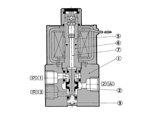
Structure drawing when not energized
The spool valve (2) is pushed upward with the reaction force of the spring (3), sealing port (P) while port (A) and port (R) are opened.
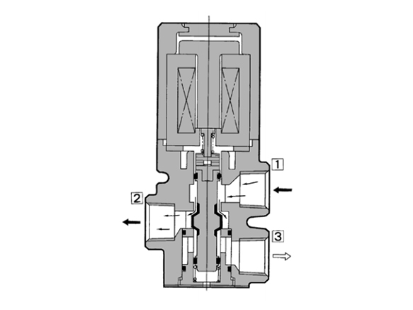
Structure drawing when energized
The armature assembly (5) is attracted to the fixed core (6), pushing down the spool valve (2) with the push rod (7). As a result, port (R) is sealed while port (P) and port (A) are opened. At this time, a gap is formed between the armature assembly (5) and the fixed core (6), but the magnetic attraction of the coil overcomes the spring force inside the armature assembly (5), causing the armature assembly (5) to be pulled into close contact with the fixed core (6).
| Number | Part name | Material | Note |
|---|---|---|---|
| 1 | Body | Die-cast aluminum | Platinum silver coated |
| 2 | Spool Valve | Aluminum, NBR | - |
Outline dimensional drawing
(Unit: mm)
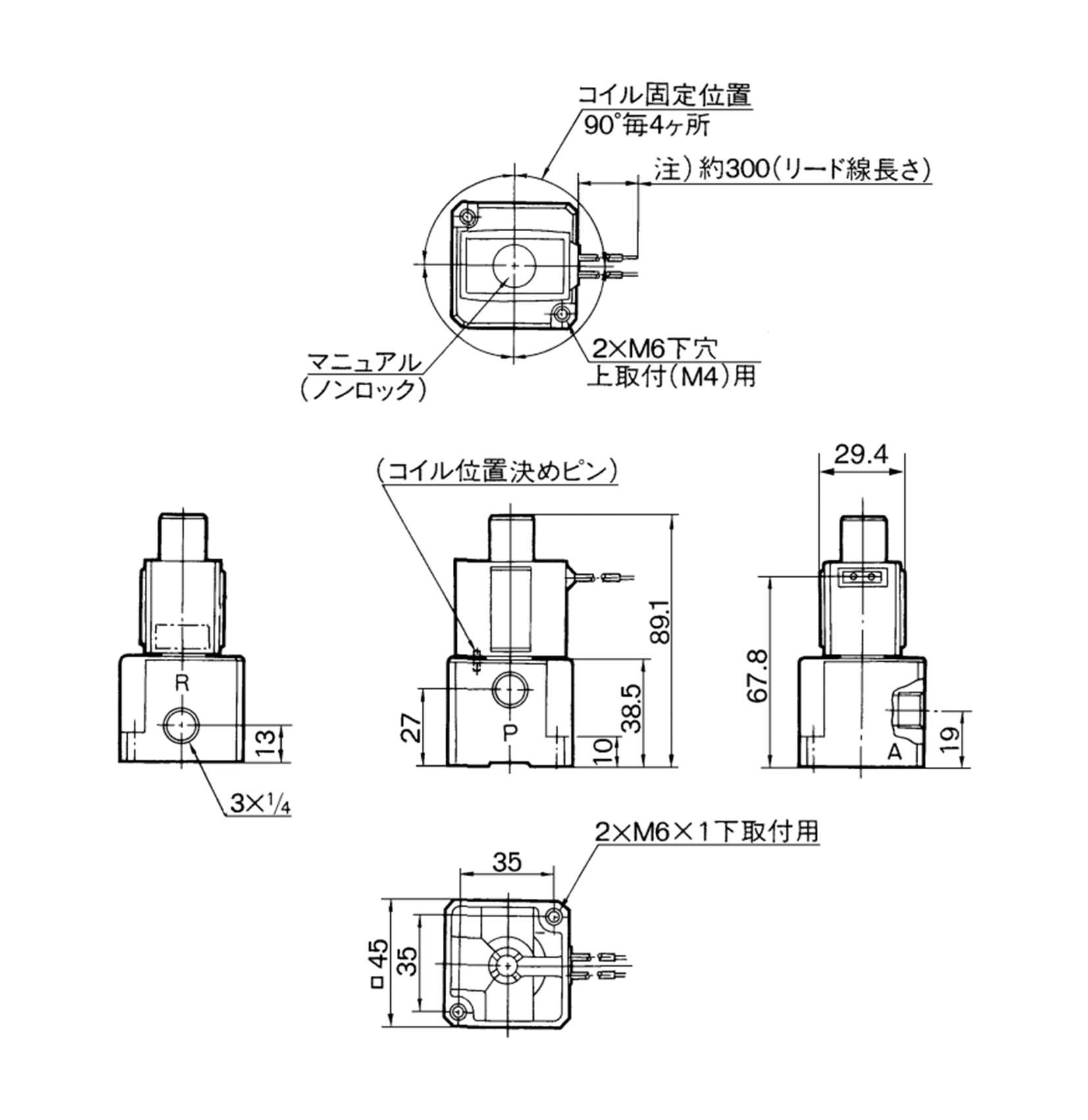
Grommet: VT317-□G dimensional drawing
*Lead wire length 600 mm (VT317-□H) also available.
(Unit: mm)
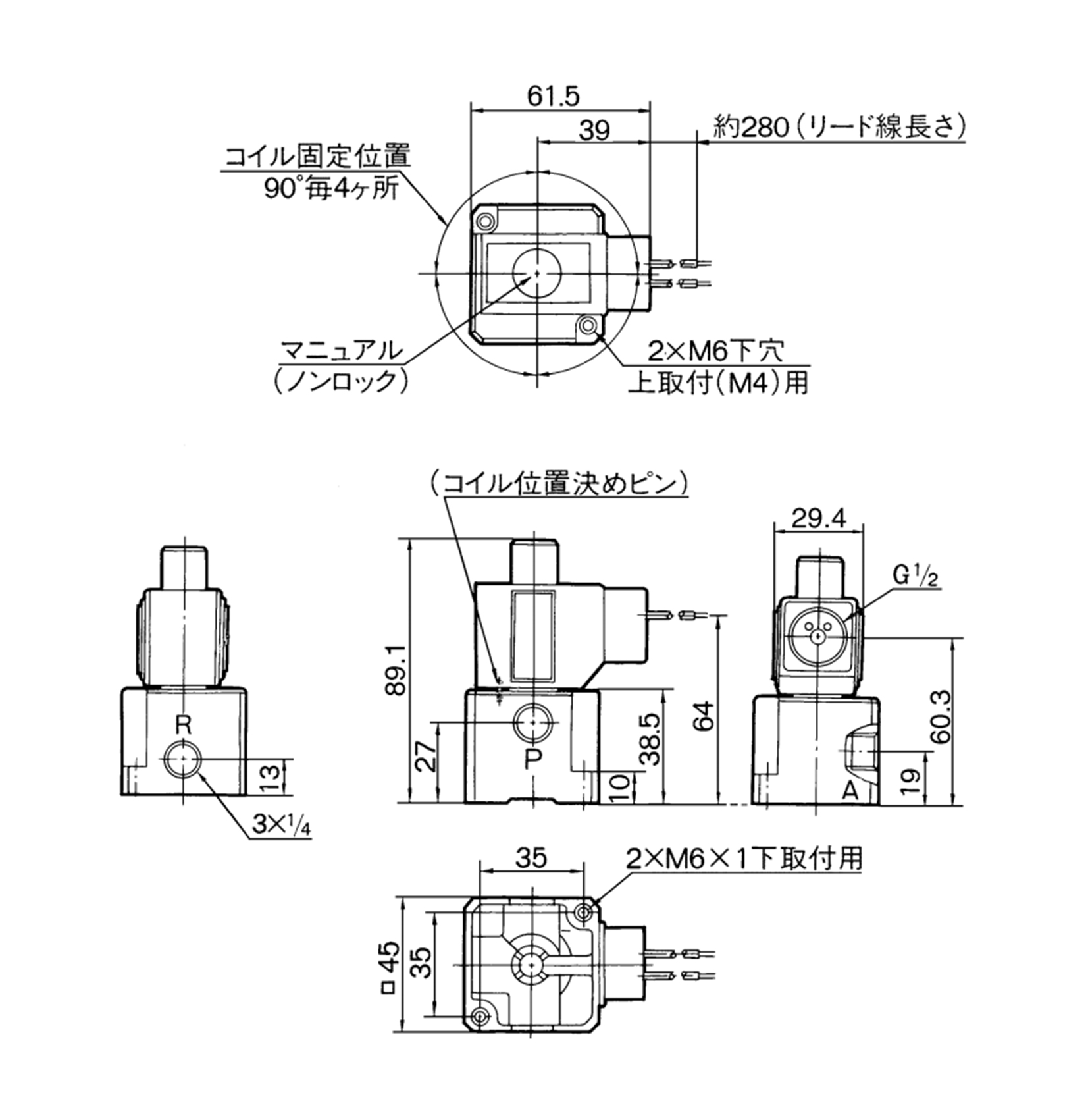
Conduit: VT317-□C dimensional drawings
(Unit: mm)
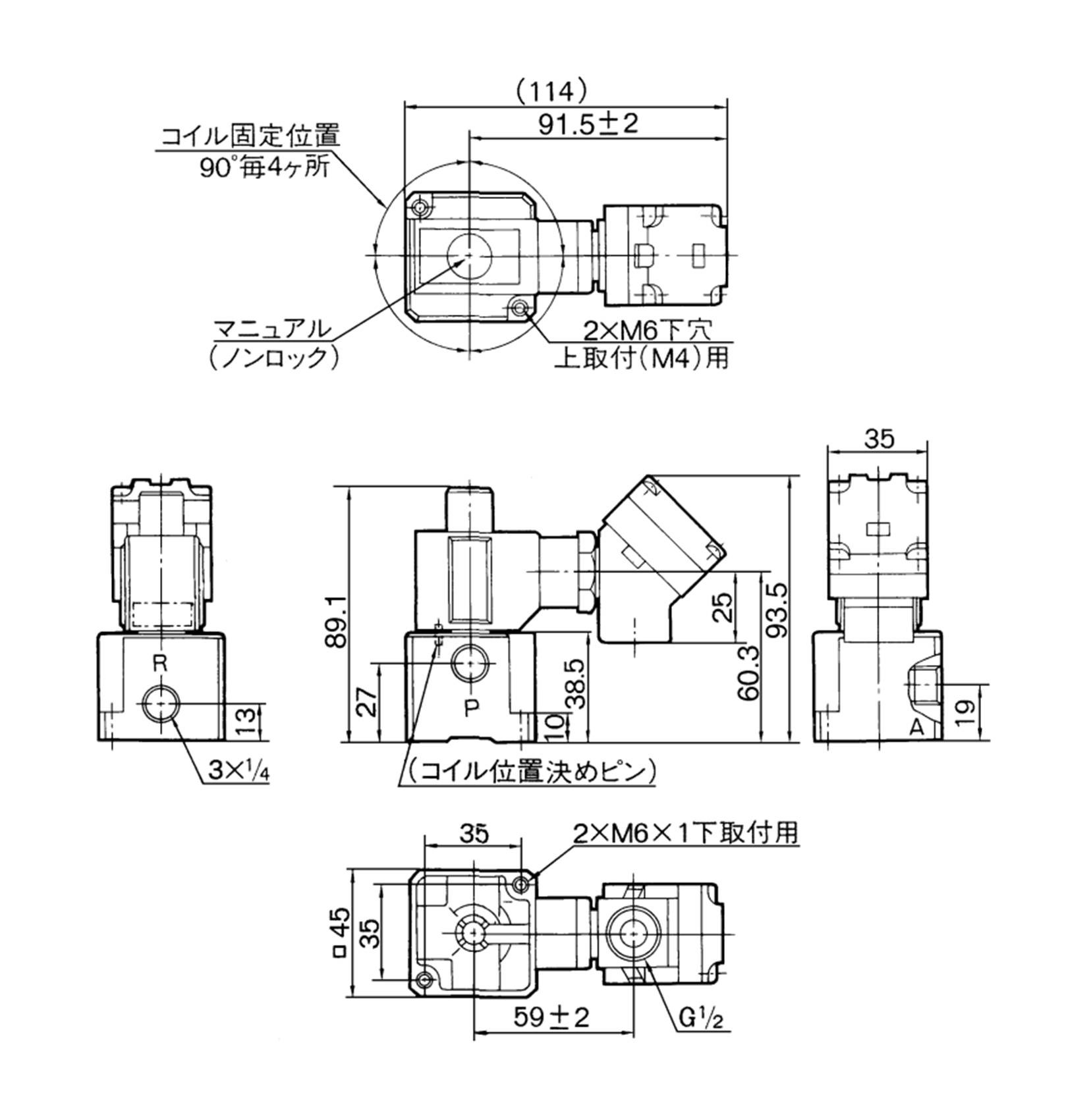
Conduit terminal: VT317-□T dimensional drawings
(Unit: mm)
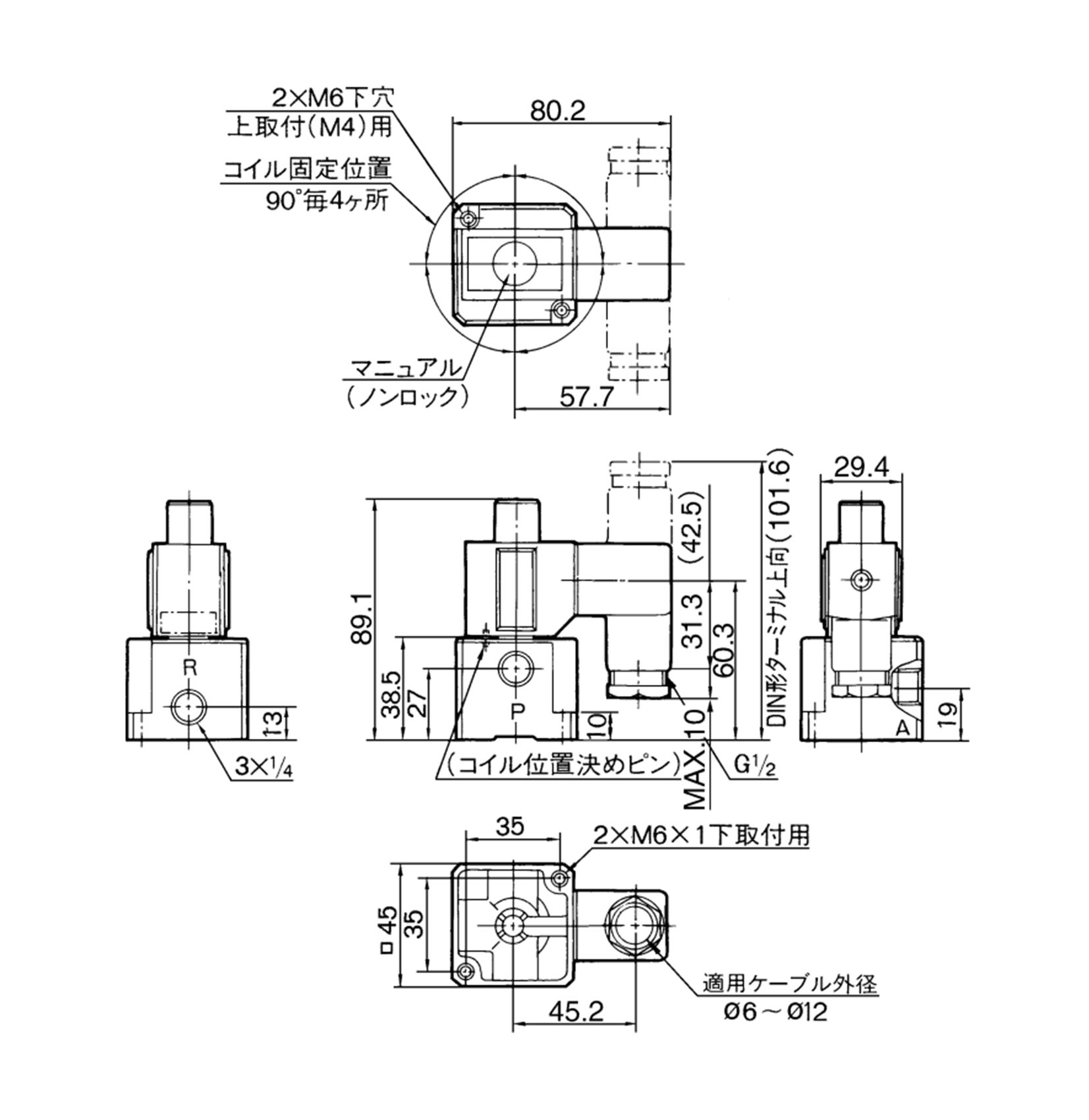
DIN terminal: VT317-□D dimensional drawings
VT317 Series Manifold Specifications
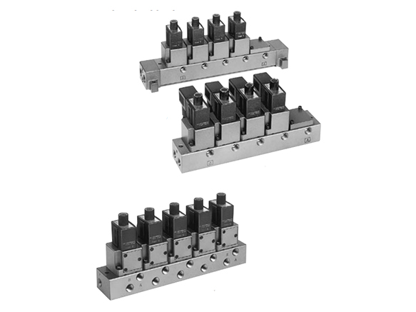
VT317 type manifold external appearance
*Pictures show representational models. This product is the valve unit only. The manifold is not included.
Manifold specifications
- Manifold type: B mount
- Maximum number of valve stations: 20 *1
- Compatible solenoid valve model: VO317□-□□□(-Q) *2
- *1When there are 3 stations or more, apply pressure from both sides of the P port. Also, in the case of a common exhaust type, exhaust from both sides of the R port.
- *2Can also be mounted to VVT320 Series manifolds.
| Exhaust port | Connecting part (direction) / Port size | |||
|---|---|---|---|---|
| Symbol | Format | P | A | R |
| 1 | Common* | Base (side) | Base (side) | Base (side) |
| 1/4 (3/8) | 1/4 | 1/4 (3/8) | ||
| 3 | Standalone | Base (side) | Base (side) | Base (side) |
| 1/4 | 1/4 | 1/4 | ||
*In the case of the common exhaust type, The P and R ports can be made 3/8 by mounting an attachment.
Flow Rate Characteristics / Weight Table
| Valve type | Flow Rate Characteristics | Weight | |||||||||||
|---|---|---|---|---|---|---|---|---|---|---|---|---|---|
| 1→2 (P→A) | 2→3 (A→R) | 3→2 (R→A) | 2→1 (A→P) | ||||||||||
| C (dm3/(s·bar)) | b | Cv | C (dm3/(s·bar)) | b | Cv | C (dm3/(s·bar)) | b | Cv | C (dm3/(s·bar)) | b | Cv | Grommet | |
| VO317 | 2.0 | 0.11 | 0.47 | 2.2 | 0.12 | 0.49 | 2.0 | 0.14 | 0.45 | 2.1 | 0.14 | 0.48 | 0.32 kg |
| VO317V (Vacuum specification) | |||||||||||||
| VO317E (Continuous duty type) | |||||||||||||
Precautions
- *1The bottom of the solenoid valve has a breather hole for the main valve. Take proper measures to prevent this hole from being blocked as this will lead to a malfunction. *Ordinarily, when the solenoid valve is mounted on a metal surface, it can breathe through the breather hole via the breather groove. However, if the surface on which it will be mounted is made of rubber, the rubber could deform and block the hole.
- *2Take proper measures to prevent dust and foreign matter from entering through unused ports, such as the exhaust port. The grommet portion contains a breather hole for the armature. Take proper measures to prevent dust or foreign matter from accumulating in this area.
Manifold specification specific product precautions
- *When mounting the valve on the manifold base, the mounting orientation is set. Mounting in the wrong direction may cause connected equipment to malfunction. When mounting, see the manufacturer's catalog regarding how to switch from a N.C. specification → N.O. specification.
- *Each valve is fixed to the manifold base with two M4 mounting screws. Tighten the screws sufficiently when re-mounting.
Mounting screw tightening torque: 1.4 N⋅m - *When mounting, tighten the M4 or equivalent screws evenly into the mounting holes of the manifold base.
Other
*See the manufacturer's catalog for information other than that above.
Référence pièce
|
|---|
| VO317-7D-Q |
| VT317-7DZ-02-Q |
| Référence pièce |
Prix unitaire standard
| Quantité minimale de commande | Remise sur volume | Application | Sens du montage | Caractéristiques | Type à commutation | Tension | Type à port de tuyau | Filetage nominal de tuyauterie | Tuyauterie | Valeur CV | Alimentation en air piloté | Témoin / Suppresseur de surtension | Conformité CE | Options de vanne | |
|---|---|---|---|---|---|---|---|---|---|---|---|---|---|---|---|---|---|
55.31 € | 1 | 26 jours | Unité de montage du collecteur | Base de collecteur | Standard | 2 positions, normalement ouvert | 240VAC | - | - | Tuyauterie de fondation | 0.47 | Interne | Aucun | Produit conforme CE | Type standard | ||
60.69 € | 1 | 26 jours | Utilisation unique | Direct | Standard | 2 positions, normalement ouvert | 240VAC | [Rc (R)] Rc | 1/4 | Tuyauterie directe | 0.62 | Interne | Avec témoin et suppresseur de surtension | Produit conforme CE | Type standard |
Loading...
Informations de base
| Type | Électrovannes | Nombre de ports | Vanne à 3 ports | Nombre de solénoïdes | Simple |
|---|---|---|---|---|---|
| État à la mise hors tension | Reprise automatique (retour de ressort) | Type d'entraînement | Clapet à mouvement linéaire | Type de joint | Joint souple |
| Pression nominale(MPa) | 0 à 0,9 | Interrupteur manuel | Non fourni | Entrée électrique du fil de sortie | Borne DIN |
Configurer
Propriétés de base
-
Application
- Utilisation unique
- Unité de montage du collecteur
-
Sens du montage
- Direct
- Base de collecteur
-
Caractéristiques
- Standard
- Sans lubrification
-
Type à commutation
- 2 positions, normalement ouvert
- Autres
-
Type à port de tuyau
- Rc (R)
- NPT
- G
- Rc (R)
-
Filetage nominal de tuyauterie
-
Tuyauterie
- Tuyauterie directe
- Tuyauterie de fondation
-
Valeur CV
-
Alimentation en air piloté
- Interne
-
Témoin / Suppresseur de surtension
- Aucun
- Avec suppresseur de surtension
- Avec témoin et suppresseur de surtension
-
Conformité CE
- Aucun
- Produit conforme CE
-
Options de vanne
- Spécification de vide
- Type standard
- Type à utilisation continue
-
Type
- VO317
- VT317
-
Tension
- 12VDC
- 24VDC
- 100VAC
- 110VAC
- 200VAC
- 220VAC
- 240VAC
-
Filtrer par type de données CAO
- 2D
- 3D
Filtrer par jours d'expédition standard
-
- Tous les articles
- 4 jours ou moins
- 16 jours ou moins
- 22 jours ou moins
- 26 jours ou moins
Propriétés optionnelles
- Les spécifications et les dimensions de certaines pièces peuvent ne pas être intégralement indiquées. Pour plus de détails, reportez-vous aux catalogues des fabricants .


