VCH410, électrovanne 3 / 2 à commande asservie 5.0 MPa pour l'air

[Features]
· Response time variation ±2 ms.
· Lifespan: 10 million cycles.
· Non-collision structure between armatures eliminates abrasion.
· Improved responsiveness when turning OFF, reduced variation construction. Improved durability achieved by applying a special surface treatment to sliding parts.
· Unnecessary volume inside the pilot chamber is reduced. Quick response, reduced variation.
· Use of impact absorbing rubber protects the pilot valve and electric parts.
· Uses a special fluoropolymer sealant on sliding parts. Stable responsiveness after disuse and not easily damaged by pressure.
· Improved durability in high-pressure environments, thanks to the polyurethane elastomer poppet.
(i)Remarque
- Les images de produits peuvent être des images représentatives. Reportez-vous au catalogue du fabricant pour les détails de forme.
Référence pièce
Vous pouvez trouver ici le numéro
de référence lié au produit recherché.
5 MPa Pilot Operated 3-Port Solenoid Valve VCH400 Series Specifications
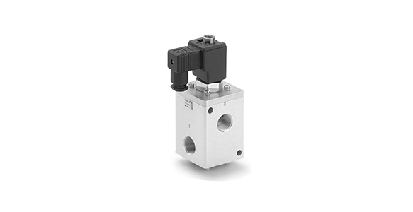
5 MPa Pilot Operated 3-Port Solenoid Valve VCH400 Series external appearance
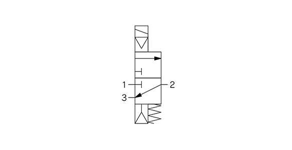
Valve type
5 MPa Pilot Operated 3-Port Solenoid Valve VCH400 Series Specifications Table
| Model | VCH410 | |||
|---|---|---|---|---|
| Valve Specifications | Valve Construction | Pilot operated poppet | ||
| Fluid | Air | |||
| Orifice equivalent diameter | ø18 (Orifice equivalent diameter 18 mm) | |||
| Flow Rate Characteristics | C value (effective cross-sectional area) | G1/2 1→2: 20 dm3/(s·bar) (100 mm2) G1/2 2→3: 22 dm3/(s·bar) (110 mm2) | G3/4, 1 1→2: 22 dm3/(s·bar) (110 mm2) G3/4, 1 2→3: 24 dm3/(s·bar) (120 mm2) | |
| b | G1/2 0.26 | G3/4, 1 0.36 | ||
| Cv | G1/2 1→2 5.3 G1/2 2→3 5.8 | G3/4, 1 1→2 5.8 G3/4, 1 2→3 6.3 | ||
| Maximum Operating Pressure | 5.0 MPa | |||
| Operating pressure differential*1 | 0.5 to 5.0 MPa | |||
| Fluid temperature | 5 to 80°C | |||
| Ambient temperature | 5 to 80°C | |||
| Body material | Aluminum alloy + hard anodized aluminum | |||
| Main valve sealing material | Polyurethane elastomer | |||
| Enclosure | Drip-proof (IP65 equivalent) | |||
| Port size | G1/2, 3/4, 1 (Compliant with ISO1179-1 G thread for pneumatics/hydraulics) | |||
| Impact resistance / Vibration resistance*2 | 300/100 m/s2 *3 | |||
| Mounting Orientation | Free | |||
| Weight | G1/2, 3/4: 1.83 kg, G1: 2.11 kg | |||
| Electrical Specifications | Voltage | 12 V, 24 V DC, 100 V, 110 V, 200 V, 220 V AC (50/60 Hz) | ||
| Allowable Voltage Fluctuation | ±10% of rated voltage | |||
| Electrical Entry | DIN terminal connector | |||
| Coil Insulation Type | Class B | |||
| Power consumption*4 | 5 W (DC), 13 VA (AC) | |||
*1: Be aware that even if the pressure differential is above the minimum operating pressure differential when the valve is closed, depending on the power of the supply source (pump, compressor, etc.) or the restriction of the ports, the pressure differential may fall below the minimum operating pressure when the valve opens.
· When used as a selector valve (pressurizing ports 1, 3) the pressure in the port should be within the range of 1 port pressure ≥ 3 port pressure ×; 2 (2 times).
· See the manufacturer's catalog for design precautions and model selection.
*2: Impact resistance: No malfunction occurred when tested using a drop tester. The test was performed once for each condition, in both energized and de-energized states, in the axial and right angle directions of the main valve/armature (initial values).
Vibration resistance: No malfunction occurred in 1 sweep test between 8.3 and 2,000 Hz. The test was performed in both energized and de-energized states in the axial and right angle directions of the main valve/armature. (Initial value)
*3: Vibration resistance is 50 m/s2 when an indicator light / surge protection circuit is attached.
*4: No inrush voltages are generated in the AC solenoid because a full-wave rectifier is used.
Response Time
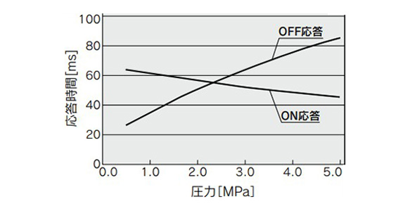
Response time / Pressure graph
*1: With DC solenoid
*2: With AC solenoid, there will be 20 to 30 ms delays to the OFF response time.
*3: Conforms to JIS B 8419-2010.
Structure
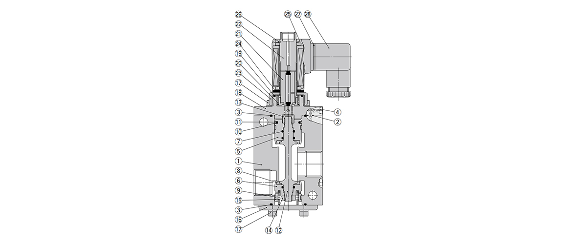
Structure Drawing
| Number | Part name | Material |
|---|---|---|
| 1 | Body | Aluminum alloy + hard anodized aluminum |
| 2 | O-ring | NBR |
| 3 | O-ring | NBR |
| 4 | Hexagon Socket Head Bolt | Stainless steel |
| 5 | Piston A | Aluminum alloy + hard anodized aluminum |
| 6 | Piston B | Aluminum alloy + hard anodized aluminum |
| 7 | O-ring | NBR |
| 8 | Poppet | Polyurethane elastomer |
| 9 | Guide ring | Resin |
| 10 | O-ring | NBR |
| 11 | Ring | Resin |
| 12 | Rod | Stainless steel |
| 13 | Hex nut | Brass |
| 14 | Hex nut type 3 | Stainless steel |
| 15 | Poppet Spring | Stainless steel |
| 16 | Plate | Steel + Electroless nickel plating |
| 17 | Hex socket head bolt (with spring lock washer) | Carbon steel |
| 18 | Bonnet | Aluminum alloy + hard anodized aluminum |
| 19 | O-ring | NBR |
| 20 | Return Spring | Stainless steel |
| 21 | Armature Assembly | - |
| 22 | Tube assembly | Stainless steel |
| 23 | Nut | Brass |
| 24 | Rubber mount | NBR |
| 25 | DIN connector type solenoid coil | - |
| 26 | Round S-shaped retaining rings | Carbon steel |
| 27 | DIN terminal gasket | CR |
| 28 | DIN terminal connector | - |
Outline dimensional drawing
(Unit: mm)
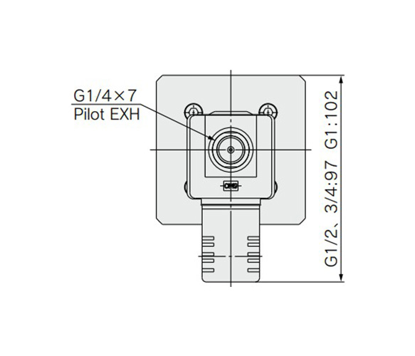
VCH410 drawing (top)
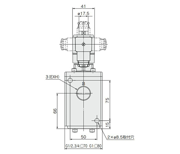
VCH410 drawing (front)
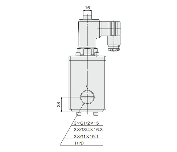
VCH410 drawing (side) 1
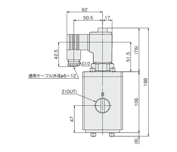
VCH410 dimensional outline drawing (side) 2
Precautions
Selection
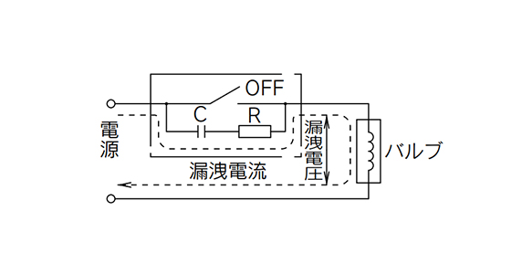
Switching element
Leakage voltage
*When the solenoid valve is operated using a controller, etc., the leakage voltage should be the product allowable voltage fluctuation or less.
In particular, when using a resistor in parallel with a switching element and using a C-R element (surge voltage suppressor) to protect the switching element, be aware that the leakage current will flow through the resistor, C-R element, etc., creating a risk that the valve will not turn OFF.
Piping
Preparation before piping
- *Before piping, it should be thoroughly blown out with air (flushing) or washed to remove chips, cutting oil or other debris.
- *Avoid pulling, compressing or bending the valve body when piping.
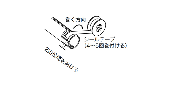
Connecting an R thread
Wrapping of sealing tape
*Sealing tape is not necessary since this product uses a pneumatic and hydraulic purpose G thread which conforms to ISO 1179-1. When an R (taper) thread is used, leave 1 to 2 threads at the tip exposed and wind the sealing tape around it 4 to 5 times.
| Port size | Proper tightening torque (N⋅m) |
|---|---|
| G, Rc1/2 | 28 to 30 |
| G, Rc3/4 | 28 to 30 |
| G, Rc1 | 36 to 38 |
Always tighten threads with the proper tightening torque
*When attaching fittings to valves, tighten to the proper tightening torque listed to the left.
- *When piping to a product, take care to avoid mistakes regarding the supply port, etc.
- *Product images may be representative images. Refer to the manufacturer's catalog for shape details.
- *See the manufacturer's catalog for product information other than the above.
Référence pièce
|
|---|
| VCH410-3D-04G-Q |
| VCH410-4D-04G-Q |
| VCH410-5D-04G-Q |
| VCH410-5DL-04G-Q |
| VCH410-6D-04G-Q |
| Référence pièce |
Prix unitaire standard
| Quantité minimale de commande | Remise sur volume | Tension | Filetage nominal de tuyauterie | Valeur CV | Entrée électrique du fil de sortie | Conformité CE | |
|---|---|---|---|---|---|---|---|---|---|
899.77 € | 1 | 26 jours | 110VAC | 1/2 | 5.3 | Connecteur de borne DIN | Produit conforme CE | ||
900.00 € | 1 | 26 jours | 220VAC | 1/2 | 5.3 | Connecteur de borne DIN | Oui | ||
900.02 € | 1 | 22 jours | 24VDC | 1/2 | 5.3 | Connecteur de borne DIN | Oui | ||
912.74 € | 1 | 26 jours | 24VDC | 1/2 | 5.3 | Borne DIN avec témoin | Oui | ||
899.77 € | 1 | 26 jours | 12VDC | 1/2 | 5.3 | Connecteur de borne DIN | Oui |
Loading...
Informations de base
| Type | Électrovannes | Application | Utilisation unique | Nombre de ports | Vanne à 3 ports |
|---|---|---|---|---|---|
| Sens du montage | Direct | Caractéristiques | Standard / Résistant aux gouttes d'eau | Nombre de solénoïdes | Simple |
| Type à commutation | 2 positions, normalement fermé | État à la mise hors tension | Reprise automatique (retour de ressort) | Type à port de tuyau | G |
| Type d'entraînement | Clapet type piloté | Type de joint | Joint souple | Alimentation en air piloté | Interne |
Configurer
Propriétés de base
-
Tension
- 12VDC
- 24VDC
- 110VAC
- 220VAC
-
Valeur CV
-
Entrée électrique du fil de sortie
- Borne DIN avec témoin
- Connecteur de borne DIN
-
Conformité CE
- Oui
- Produit conforme CE
-
Type
- VCH410
-
Filetage nominal de tuyauterie
-
Filtrer par type de données CAO
- 2D
- 3D
Filtrer par jours d'expédition standard
-
- Tous les articles
- 4 jours ou moins
- 22 jours ou moins
- 26 jours ou moins
Propriétés optionnelles
- Les spécifications et les dimensions de certaines pièces peuvent ne pas être intégralement indiquées. Pour plus de détails, reportez-vous aux catalogues des fabricants .


