JT, Joint de compensation, Standard, Léger et compact

[Features]
・ Maximum weight reduced by 56%.
· Screw size is the same as the screw size for standard JA Series.
· More compact and lightweight combinations are possible by using the JT Series with a JCM Series cylinder.
· With dustproof cover.
· Operating pressure: pneumatic cylinder.
· Mounting: basic type.
(i)Remarque
- Product images may be representative images. Refer to the manufacturer's catalog for details
Référence pièce
Vous pouvez trouver ici le numéro
de référence lié au produit recherché.
JT Series Standard/Lightweight And Compact Type Floating Joint Specifications
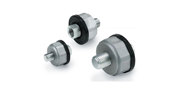
JT Series Floating Joint external appearance
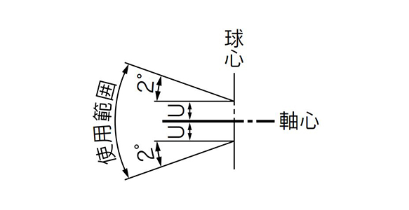
JT Series Floating Joint operating range
| Model | Nominal thread size | Allowable axial force (N) | Allowable eccentricity U (mm) | Rotating angle (°) | Operating temperature range |
|---|---|---|---|---|---|
| JT20 | M8 ×; 1.25 | 220 | 0.5 | ±2 | -10 to +70°C |
| JT32 | M10 ×; 1.25 | 560 | 0.5 | ±2 | |
| JT40 | M14 ×; 1.5 | 880 | 0.75 | ±2 |
(Standard Type / Pneumatic: Up to 0.7 MPa) Dimensions
(Unit: mm)
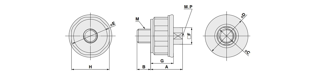
JT Series Floating Joint dimensional drawing
| Model | Port size M | A | B | øC | øD | øE | □F | G | Width across flats H | Maximum thread depth P | Weight |
|---|---|---|---|---|---|---|---|---|---|---|---|
| JT20 | M8 ×; 1.25 | 19.2 | 8 | 11 | (25.4) | 23 | 10 | 13.6 | 22 | 9.5 | 22 g |
| JT32 | M10 ×; 1.25 | 23 | 10 | 13.4 | (30.6) | 28 | 12 | 16.3 | 27 | 11.5 | 38 g |
| JT40 | M14 ×; 1.5 | 29 | 14 | 19 | (40.4) | 37.4 | 17 | 20.3 | 36 | 15.5 | 98 g |
*Value in ( ) is the dimension when the dust cover is used.
Compatible Cylinder
(Unit: mm)
| Model | Compatible cylinder* | Recommended cylinder | ||
|---|---|---|---|---|
| Bore size | Operating pressure | |||
| JT20 | ø20 (bore size 20 mm) | 0.7 MPa or less | JC□M20 (rod end male thread type) | |
| JT32 | ø25 (bore size 25 mm) | JC□M25 (rod end male thread type) | ||
| ø32 (bore size 32 mm) | JC□M32 (rod end male thread type) | |||
| JT40 | ø40 (bore size 40 mm) | JC□M40 (rod end male thread type) | ||
*Make sure to use a cylinder with a built-in cushion mechanism.
Diagram
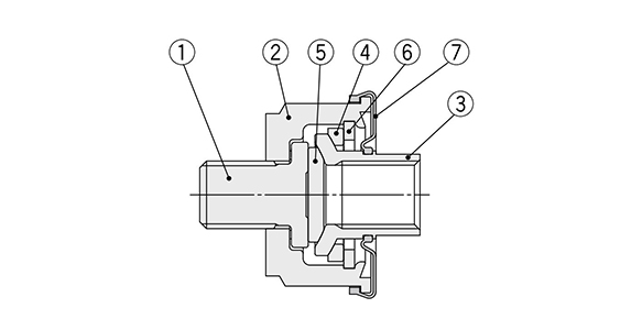
JT Series Floating Joint Diagram
| Number | Description | Material | Note |
|---|---|---|---|
| 1 | Stud | Carbon steel | Zinc chromate |
| 2 | Case | Aluminum alloy | Chromate |
| 3 | Socket | Carbon steel | Zinc chromate |
| 4 | Ring | Rolled steel | Nitriding treatment |
| 5 | Slider | Rolled steel | Nitriding treatment |
| 6 | Plate | Rolled steel | Zinc chromate |
| 7 | Dust cover | Synthetic rubber | - |
Replacement part (No. 7 / dust cover) compatible model
- P215420-07: JT20
- P215432-07: JT32
- P215440-07: JT40
Mounting Precautions
- *1Maintenance space
Allow sufficient space for maintenance and inspection. - *2Operate the socket by hand before mounting to ensure it moves smoothly.
The dust cover may stick to the socket. Move the dust cover at the base of the socket with your fingers, or twist the socket right and left gently to free it before mounting. - *3Tighten the product to the appropriate torque for the screw size using an appropriate tool. In addition, apply a locking adhesive.
When connecting the driven object to the cylinder rod with a floating joint, hold the octagonal and square parts with an appropriate wrench and tighten the floating joint to the appropriate tightening torque according to the table below.
The floating joint may be broken or malfunction if parts other than the octagonal or square parts are gripped and rotated with pliers or a wrench, or if it is tightened to an excessive torque.
As a countermeasure against loosening caused by vibration or other reasons, apply locking adhesive. - *4See the manufacturer's catalog for product information other than the above.

Reference drawing for correct mounting of JT Series Floating Joint
- *Tighten with the rod end nut attached to the cylinder.
- *Screw the floating joint all the way to the end face.
| Model | Stud (male thread side) | Socket (female thread side) | ||
|---|---|---|---|---|
| Wrench size (bowl) | Tightening torque | Wrench size (socket) | Tightening torque | |
| JT20 | Width 22 mm | 12 N・m | Width 10 mm | 8 to 12 N・m |
| JT32 | Width 27 mm | 24 N・m | Width 12 mm | 15 to 24 N・m |
| JT40 | Width 36 mm | 68 N・m | Width 17 mm | 40 to 68 N・m |
Référence pièce
|
|---|
| JT20 |
| JT32 |
| JT40 |
| Référence pièce |
Prix unitaire standard
| Quantité minimale de commande | Remise sur volume | Filetage de connexion nominal M (mm) | Max. Force de traction de fonctionnement (kN) | Désalignement U admissible (mm) | Taille d'alésage de vérin applicable (ø) | Filetage nominal de vérin applicable | |
|---|---|---|---|---|---|---|---|---|---|
21.47 € | 1 | 4 jours | M3 à M8 | 0.22 | 0.5 | Pour ø20 | M8 × 1.25 | ||
22.84 € | 1 | 4 jours | M10 à M18 | 0.56 | 0.5 | Pour ø25, ø32 | M10 × 1.25 | ||
30.21 € | 1 | 26 jours | M10 à M18 | 0.88 | 0.75 | Pour ⌀40 | M14 × 1.5 |
Loading...
Informations de base
| Type | Joints flottants | Cylindre utilisé | Cylindre pneumatique | Type de connexion, côté cylindre | Filetages |
|---|---|---|---|---|---|
| Filetage de connexion nominal P(mm) | 1 à 1,75 | Type de connexion, côté pièce à usiner | Taraudé | Matériau du corps principal | Acier au carbone |
| Tête métallique | Non fourni | Matériau du goujon | Acier | Plage de températures de fonctionnement(°C) | -10::70 |
| Désalignement angulaire admissible V(deg) | ±2 |
Configurer
Propriétés de base
-
Filetage de connexion nominal M(mm)
- M3 à M8
- M10 à M18
-
Désalignement U admissible(mm)
-
Taille d'alésage de vérin applicable(ø)
- Pour ø20
- Pour ø25, ø32
- Pour ⌀40
-
Filetage nominal de vérin applicable
- M8 × 1.25
- M10 × 1.25
- M14 × 1.5
-
Type
-
Filtrer par type de données CAO
- 2D
- 3D
Filtrer par jours d'expédition standard
-
- Tous les articles
- 4 jours ou moins
- 26 jours ou moins
Propriétés optionnelles
- Les spécifications et les dimensions de certaines pièces peuvent ne pas être intégralement indiquées. Pour plus de détails, reportez-vous aux catalogues des fabricants .
Assistance technique
Mode de paiement


Fabrication à la demande
Certificats


Copyright © MISUMI Corporation All Rights Reserved.