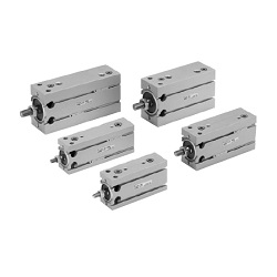
C(D)U-A, Vérin à montage libre à amortisseurs de chocs (CDU25-80A)
Détails du produit:
Référence fabricant: CDU25-80A
Marque: SMC
Prix: 139.76 €
Délai de livraison: 4 jours
Données techniques:
D.I. du cylindre : D: 25 Ø
Course : L: 80 mm
Température de fonctionnement: -10~70 ℃
Pression de fonctionnement: 0.08~0.7 MPa
Port thread type: M5 × 0.8
(i)Remarque
- ■ SMC Product Line
Webpages for products currently without individual pages on this site will be released on an ad-hoc basis. - Refer to the manufacturer's catalog for specification and material details.
- Product images may be representative images. Refer to the manufacturer's catalog for shape details.
Référence pièce
Vous pouvez trouver ici le numéro
de référence lié au produit recherché.
CDU25-80A
CU Series Free Mount Cylinder With Air Cushion
| Model | Pneumatic (non-lube) type |
|---|---|
| Fluid | Air |
| Proof Pressure | 1.0 MPa |
| Maximum operating pressure | 0.7 MPa |
| Minimum operating pressure | 0.08 MPa |
| Ambient and Fluid Temperature | Without auto switch: -10°C to +70 ℃ (no freezing) |
| With auto switch: -10°C to +60 ℃ (no freezing) | |
| Rod-end thread | Male thread |
| Stroke Length Tolerance | 0 to +1.0 |
| Operating piston speed | 50 to 500 mm/s |
Effective Cushion Length
- Bore size 20 mm: effective cushion length 6.6 mm
- Bore size 25 mm: effective cushion length 6.7 mm
- Bore size 32 mm: effective cushion length 7.7 mm
Standard Stroke Table
Bore size 20 mm, 25 mm, 32 mm: standard stroke 20 mm, 30 mm, 40 mm, 50 mm, 60 mm, 70 mm, 80 mm, 90 mm, 100 mm
Diagram
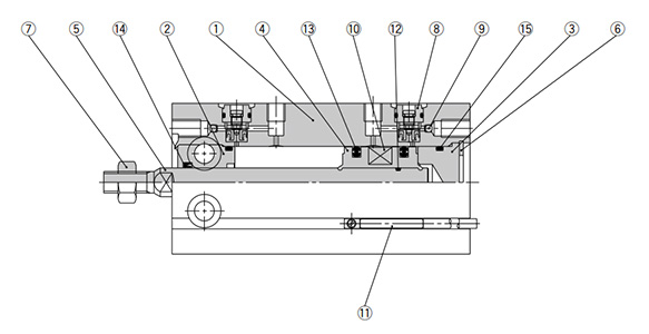
Diagram: CU Series
| Number | Part Name | Material | Quantity | Notes |
|---|---|---|---|---|
| 1 | Cylinder Tube | Aluminum alloy | 1 | Hard anodized aluminum |
| 2 | Rod cover | Aluminum alloy | 1 | Hard anodized aluminum |
| 3 | Head cover | Aluminum alloy | 1 | Chromate |
| 4 | Piston | Aluminum alloy | 1 | Chromate |
| 5 | Piston rod | Stainless steel | 1 | - |
| 6 | Retaining Ring | Carbon tool steel | 1 | Phosphate conversion coating |
| 7 | Rod end nut | Carbon steel | 1 | Chromate |
| 8 | Cushion needle assembly | - | (2) | - |
| 9 | Steel ball | Carbon steel | 2 | - |
| 10 | Magnet | - | 1 | - |
| 11 | Auto switch | - | (2) | - |
| 12 | Piston gasket | NBR | 1 | - |
| 13 | Piston packing | NBR | 2 | - |
| 14 | Rod packing | NBR | 1 | - |
| 15 | Gasket | NBR | 1 | - |
Drawing
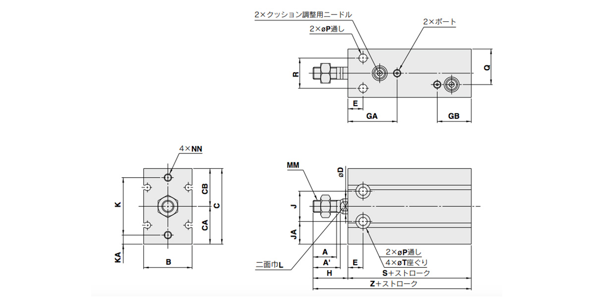
Dimensional drawings: CU Series Free Mount Cylinder With Air Cushion
(Units: mm)
| Tube inner diameter (mm) | Port | A | A' | B | C | CA | CB | D | E | GA | GB | H | J | JA |
|---|---|---|---|---|---|---|---|---|---|---|---|---|---|---|
| 20 | M5 ×; 0.8 | 12 | 14 | 26 | 42 | 20 | 22 | 8 | 9 | 29 | 27 | 19 | 16 | 12 |
| 25 | M5 ×; 0.8 | 15.5 | 18 | 32 | 50 | 25 | 25 | 10 | 10 | 32.5 | 22.5 | 23 | 20 | 15 |
| 32 | 1/8 | 19.5 | 22 | 40 | 62 | 31 | 31 | 12 | 11 | 35 | 25 | 27 | 24 | 19 |
(Units: mm)
| Tube inner diameter (mm) | K | KA | L | MM | NN | P | Q | R | T | S | Z | Standard Stroke |
|---|---|---|---|---|---|---|---|---|---|---|---|---|
| 20 | 30 | 5 | 6 | M6 ×; 1.0 | M5 ×; 0.8 depth 8 | 5.5 | 13 | 16 | 9.3 depth 8 | 53 | 72 | 20, 30, 40, 50, 60, 70, 80, 90, 100 |
| 25 | 38 | 6 | 8 | M8 ×; 1.25 | M5 ×; 0.8 depth 8 | 5.5 | 23.5 | 20 | 9.3 depth 9 | 51.5 | 74.5 | |
| 32 | 48 | 7 | 10 | M10 ×; 1.25 | M6 ×; 1.0 depth 9 | 6.6 | 29 | 24 | 11 depth 11.5 | 56 | 83 |
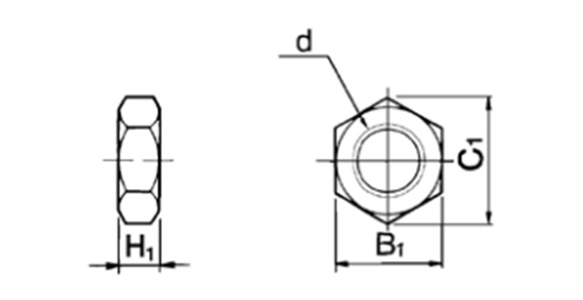
Dimensional drawings: rod-end nut / accessory
(Units: mm)
| Part No. | Applicable Tube Bore Size (mm) | d | H1 | B1 | C1 |
|---|---|---|---|---|---|
| NT-015A | 20 | M6 ×; 1.0 | 5 | 10 | 11.5 |
| NT-02 | 25 | M8 ×; 1.25 | 5 | 13 | 15.0 |
| NT-03 | 32 | M10 ×; 1.25 | 6 | 17 | 19.6 |
Material: carbon steel
Proper Auto Switch Mounting Position (Detection at Stroke End) and Mounting Height
(Units: mm)
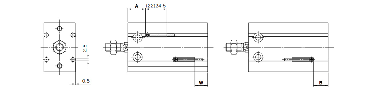
Dimensional drawings: D-A9□/D-M9□/D-M9□W/D-M9□A
*( ): denotes the values of D-A96.
(Units: mm)
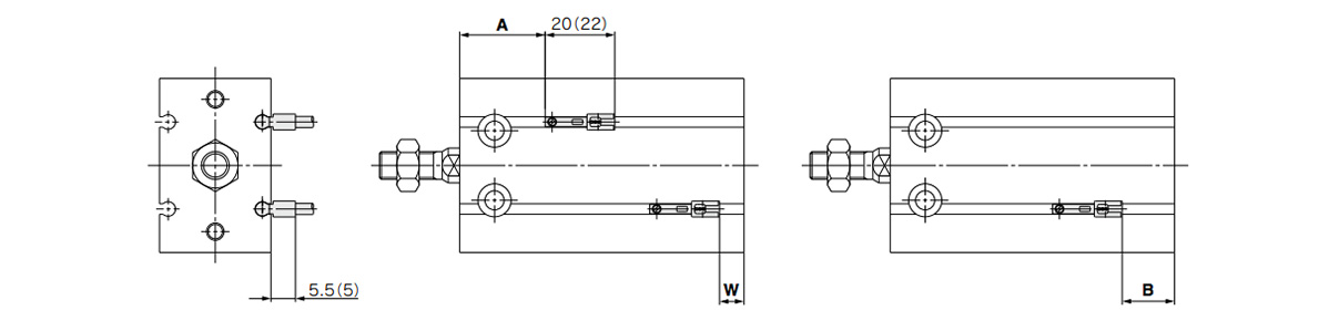
Dimensional drawings: D-A9□V/D-M9□V/D-M9□WV/D-M9□AV
*( ): denotes the values of D-M9□V/D-M9□WV.
(Units: mm)
| Tube inner diameter (mm) | D-A9□, D-A9□V | D-M9□, D-M9□W | D-M9□V, D-M9□WV | D-M9□A | D-M9□AV | ||||||||||
|---|---|---|---|---|---|---|---|---|---|---|---|---|---|---|---|
| A | B | W | A | B | W | A | B | W | A | B | W | A | B | W | |
| 20 | 18 | 15 | 13 (10.5) | 22 | 19 | 9 | 22 | 19 | 11 | 22 | 19 | 11 | 22 | 19 | 13 |
| 25 | 20 | 11 | 9 (6.5) | 24.5 | 15 | 5 | 24.5 | 15 | 7 | 24.5 | 15 | 7 | 24.5 | 15 | 9 |
| 32 | 22.5 | 13.5 | 11.5 (9) | 26.5 | 17.5 | 7.5 | 26.5 | 17.5 | 9.5 | 26.5 | 17.5 | 9.5 | 26.5 | 17.5 | 11.5 |
- *1Figures in the table above are used as a reference when mounting the auto switches for stroke end detection. When actually setting the auto switches, adjust them after confirming their operation.
- *2Values in ( ) under column W are dimensions for the D-A90 and D-A93 type.
Operating Range
D-A9□, D-A9□V
Bore size 20 mm: 11 mm / Bore size 25 mm: 12.5 mm / Bore size 32 mm: 14 mm
D-M9□, D-M9□V, D-M9□W, D-M9□WV, D-M9□A, D-M9□AV
Bore size 20 mm: 7 mm / Bore size 25 mm: 7 mm / Bore size 32 mm: 7.5 mm
*The operating range is provided as a guideline that includes hysteresis and is not a guaranteed value (assuming approximately ±30% dispersion). It may vary substantially depending on the ambient environment.
Mounting
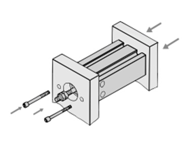
Axial mounting (body tapped)
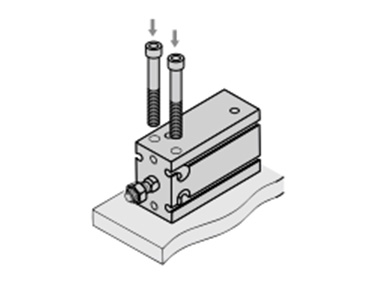
Vertical mounting (body through-holes)
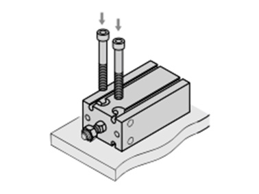
Lateral mounting (body through-holes)
Precautions
Installation and Removal of Retaining Rings
- *Use an appropriate pair of pliers (tool for installing a type C retaining ring) for installation and removal of retaining rings.
- *Even when using an appropriate pair of pliers (tool for installing a type C retaining ring), proceed with caution as there is a danger of the retaining ring flying off the end of the pliers (tool) and causing bodily injury or damage to nearby equipment. After installation, make sure that the retaining ring is securely seated into the retaining ring groove before supplying air.
Selection
- *Operate the cylinder to the stroke end. When the stroke is restricted by an external stopper or a clamped workpiece, sufficient cushioning and noise reduction may not be achieved.
- *Strictly observe the limiting ranges for load weight and maximum speed (Graph 1). Also, the limiting ranges provided here are based on the condition that the cylinder is operated to the stroke end with proper cushion needle adjustment. If operated beyond the limiting ranges, excessive impact will occur and this may cause damage to equipment.
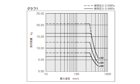
Limiting ranges for load weight and maximum speed (Graph 1)
*See the manufacturer's catalog for product information other than that detailed above.
Référence pièce
|
|---|
| CDU25-80A |
| Référence pièce |
Prix unitaire standard
| Quantité minimale de commande | Remise sur volume | D.I. du cylindre : D (Ø) | Course : L (mm) | Température de fonctionnement (℃) | Pression de fonctionnement (MPa) | Port thread type | Auto Switch | Lead Wire Length (m) | Number of Switches | |
|---|---|---|---|---|---|---|---|---|---|---|---|---|
139.76 € | 1 | 4 jours | 25 | 80 | -10~70 | 0.08~0.7 | M5 × 0.8 | Sans commutateur auto (aimant intégré) | Aucun | Aucun |
Loading...
Informations de base
| Méthode de fonctionnement du cylindre | Double effet | Méthode de fonctionnement de la tige | Tiges simples | Forme du corps principal | Cylindre de plaque |
|---|---|---|---|---|---|
| Fonction supplémentaire | Standard | Environnement, applications | Standard | Verrouillage d'extrémité | NA |
| Soupapes | NA | Type de connecteur | Aucun |
Vous vous trouvez sur la page de C(D)U-A, Vérin à montage libre à amortisseurs de chocs, le numéro d'article est le suivant: CDU25-80A.
Veuillez trouver plus de détails concernant les particularités et les dimensions sous le numéro d'article CDU25-80A.
Configurer
Propriétés de base
-
Type
- CDU20□
- CDU25□
- CDU32□
- CU20□
- CU25□
- CU32□
-
D.I. du cylindre : D(Ø)
-
Course : L(mm)
-
Port thread type
- G 1/8
- Rc 1/8
- M5 × 0.8
- M5 × 0.8
-
Auto Switch
- M9BW
- M9N
- M9P
- A93
- Sans commutateur auto
- Sans commutateur auto (aimant intégré)
-
Lead Wire Length(m)
- 0.5
- 3
- Aucun
-
Number of Switches
- 2 pcs
- Aucun
-
Filtrer par type de données CAO
- 2D
- 3D
Filtrer par jours d'expédition standard
-
- Tous les articles
- 4 jours ou moins
- 26 jours ou moins
Propriétés optionnelles
- Les spécifications et les dimensions de certaines pièces peuvent ne pas être intégralement indiquées. Pour plus de détails, reportez-vous aux catalogues des fabricants .
Variantes de ce produit
| Référence pièce |
|---|
| CDU20-20A |
| CDU20-30A |
| CDU20-40A |
| CDU25-90A |
| CDU32-100A |
| CDU32-100A-M9BW |
| Référence pièce | Prix unitaire standard | Quantité minimale de commande | Remise sur volume | Jour d'expédition standard ? | D.I. du cylindre : D (Ø) | Course : L (mm) | Température de fonctionnement (℃) | Pression de fonctionnement (MPa) | Port thread type | Auto Switch | Lead Wire Length (m) | Number of Switches |
|---|---|---|---|---|---|---|---|---|---|---|---|---|
112.52 € | 1 | 4 jours | 20 | 20 | -10~70 | 0.08~0.7 | M5 × 0.8 | Sans commutateur auto (aimant intégré) | Aucun | Aucun | ||
113.61 € | 1 | 4 jours | 20 | 30 | -10~70 | 0.08~0.7 | M5 × 0.8 | Sans commutateur auto (aimant intégré) | Aucun | Aucun | ||
114.74 € | 1 | 4 jours | 20 | 40 | -10~70 | 0.08~0.7 | M5 × 0.8 | Sans commutateur auto (aimant intégré) | Aucun | Aucun | ||
140.82 € | 1 | 26 jours | 25 | - | -10~ 70 | 0.08~ 0.7 | M5 × 0.8 | Sans commutateur auto (aimant intégré) | Aucun | Aucun | ||
184.11 € | 1 | 26 jours | 32 | - | -10~ 70 | 0.08~ 0.7 | Rc 1/8 | Sans commutateur auto (aimant intégré) | Aucun | Aucun | ||
251.73 € | 1 | 26 jours | 32 | - | - | 0.08~ 0.7 | Rc 1/8 | M9BW | 0.5 | 2 pcs |
Assistance technique
Mode de paiement


Fabrication à la demande
Certificats


Copyright © MISUMI Corporation All Rights Reserved.