Vanne de vapeur, vanne à 2 ports pour la vapeur gamme VND

[Features]
· Use of a PTFE seal makes it suitable for steam.
· Large valve capacity.
· Wide variations.
· With indicator (option)
· Cylinder operated by external pilot air.
· With PTFE seal.
(i)Remarque
- Product images may be representative images. Refer to the catalog for details.
Référence pièce
Vous pouvez trouver ici le numéro
de référence lié au produit recherché.
2 Port Valve For Steam, Steam Valve, VND Series Specifications

2 Port Valve For Steam, Steam Valve, VND Series external appearance
| Model | Piping Connection Port Diameter | Orifice Diameter ø (mm) | Flow Rate Characteristics | Weight (kg) | ||
|---|---|---|---|---|---|---|
| Thread | Flange* | Kv | Conversion Cv | |||
| VND10□D-6A | 1/8 | - | 7 | 0.9 | 1.1 | 0.3 |
| VND10□D-8A | 1/4 | - | 1.0 | 1.2 | ||
| VND10□D-10A | 3/8 | - | 1.1 | 1.3 | ||
| VND20□D-10A | - | 15 | 4.3 | 5.0 | 0.6 | |
| VND20□D-15A | 1/2 | - | 4.6 | 5.4 | ||
| VND30□D-20A | 3/4 | - | 20 | 8.6 | 9.9 | 0.9 |
| VND40□D-25A | 1 | - | 25 | 13.6 | 16 | 1.4 |
| VND50□D-32A | 1 1/4 | - | 32 | 15.7 | 18 | 2.3 |
| VND50□D-32F | - | 32 | 5.5 | |||
| VND60□D-40A | 1 1/2 | - | 40 | 32.9 | 38 | 3.6 |
| VND60□D-40F | - | 40 | 7.2 | |||
| VND70□D-50A | 2 | - | 50 | 53.6 | 62 | 5.7 |
| VND70□D-50F | - | 50 | 10.8 | |||
*The accompanying flange should be JIS B 2210 10K (ordinary) or its equivalent
Specifications
| Fluid (Main Piping) | Steam | ||
|---|---|---|---|
| Fluid Temperature | *1 -5 to 180°C | ||
| Ambient Temperature | *1: -5 to 60°C | ||
| Proof Pressure | 1.5 MPa | ||
| Operating Pressure Range | 0 to 0.97 MPa | ||
| External Pilot Air | Pressure | N.C. Type | 0.3 to 0.7 MPa |
| N.O. Type | 0.1 + 0.25 ×; (operating pressure) to 0.25 + 0.25 ×; (operating pressure) MPa - See table (1) | ||
| Lubrication | Not required | ||
| Temperature | *1: -5 to 60°C | ||
| Mounting Orientation | Free | ||
*1 No freezing.
*2 The non-lubricated specification are not available for these models.
JIS symbol
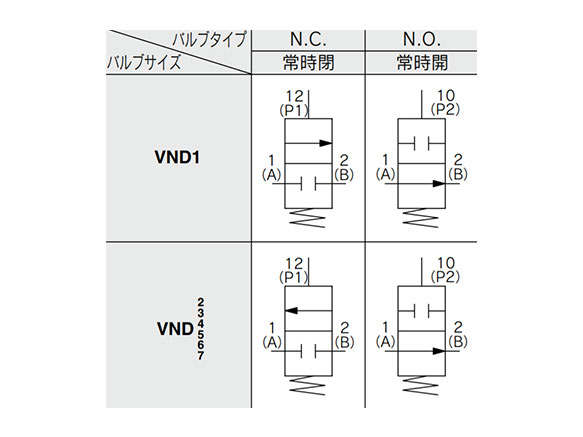
JIS symbol
Table 1. VND□02D Pilot Pressure Valve Type (N.O. Type)
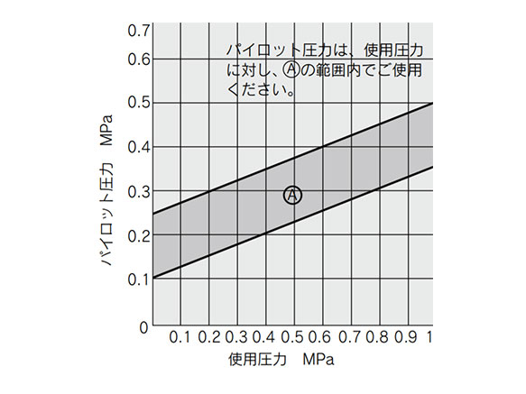
VND□02D pilot pressure valve type (N.O. type) pressure graph
*Keep the pilot pressure within range A against the operating pressure.
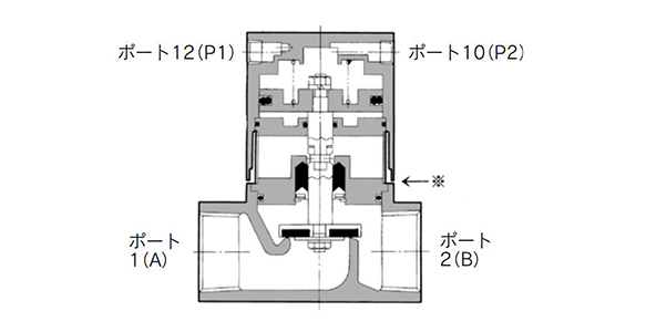
Diagram
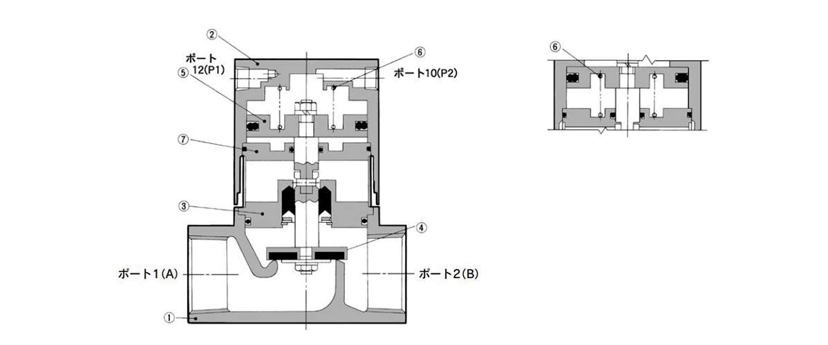
N.C. type (left drawing) / N.O. type (right drawing) diagram
Component Parts
| Number | Part Name | Material | Notes |
|---|---|---|---|
| 1 | Body | *Bronze | Clear coating |
| 2 | Cover Assembly | Aluminum alloy | Platinum silver coated |
| 3 | Plate Assembly | *Brass | PTFE/EPR/FKM |
| 4 | Valve Element | *Brass, PTFE | - |
| 5 | Piston Assembly | Aluminum alloy | - |
| 6 | Return Spring | Piano wire | - |
| 7 | Second Plate Assembly | Aluminum alloy | - |
*Body option S is stainless steel.
Operating Principle
For VND□00/04□ (N.C. Type)
When air is exhausted from 12 (P1) port, valve 4 linked to piston 5 is closed via the action of the return spring 6.
- For Opening the Valve
When pressurized air enters through port 12 (P1), the pilot air that has entered under the piston moves upward, opening the valve. - For Closing the Valve
When fluid is exhausted from port 12 (P1), the pilot air under the piston is exhausted and the valve closed via the action of the return spring.
For VND□02□ (N.O. Type)
In contrast for the N.C. type, when air is exhausted from port 10 (P2), the valve is held open via the return spring. Pressurized air through port 10 (P2) closes the valve.
Dimensions/Diagram
(Units: mm)
Piping Connection Port Diameter: 6A, 8A, 10A
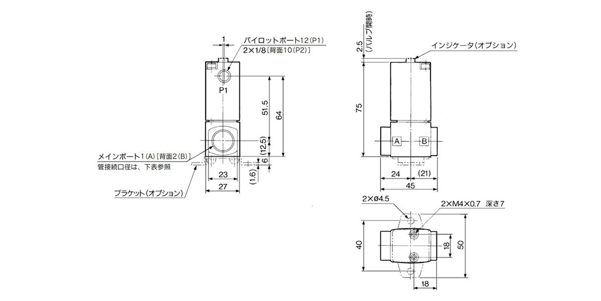
Piping connection port diameter: 6A, 8A, 10A dimensions and diagram
- VND10□D-6A: main port 1 (A), 2 (B) 1/8
- VND10□D-8A: main port 1 (A), 2 (B) 1/4
- VND10□D-10A: main port 1 (A), 2 (B) 3/8
Piping Connection Port Diameter: 10A, 15A, 20A, 25A
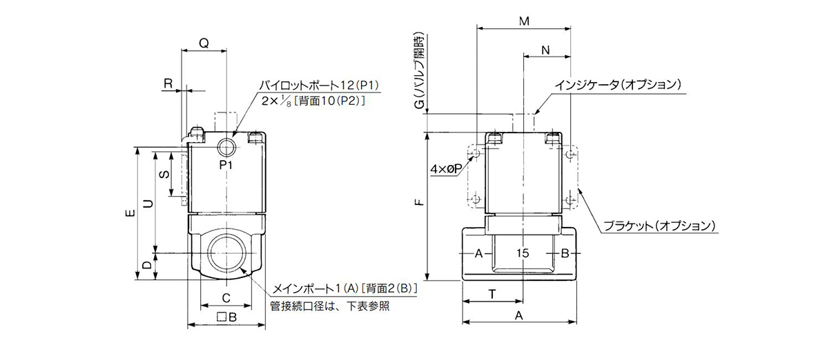
Piping connection port diameter: 10A, 15A, 20A, 25A dimensions and diagram
| Model | Main Port 1 (A), 2 (B) | A | B | C | D | E | F | G | M | N | P | Q | R | S | T | U |
|---|---|---|---|---|---|---|---|---|---|---|---|---|---|---|---|---|
| VND20□D-10A | 3/8 | 63 | 42 | 28 | 14 | 73.5 | 81.5 | 4 | 52 | 26 | 4.5 | 24.3 | 2.3 | 25 | 34 | 56 |
| VND20□D-15A | 1/2 | |||||||||||||||
| VND30□D-20A | 3/4 | 80 | 50 | 35 | 17.5 | 85 | 93 | 5 | 62 | 31 | 5.5 | 28.3 | 2.3 | 30 | 43 | 61.5 |
| VND40□D-25A | 1 | 90 | 60 | 44 | 22 | 101 | 109 | 6 | 72 | 36 | 6.5 | 33.3 | 2.3 | 35 | 49 | 74 |
Piping connection port diameter: 32A, 40A, 50A
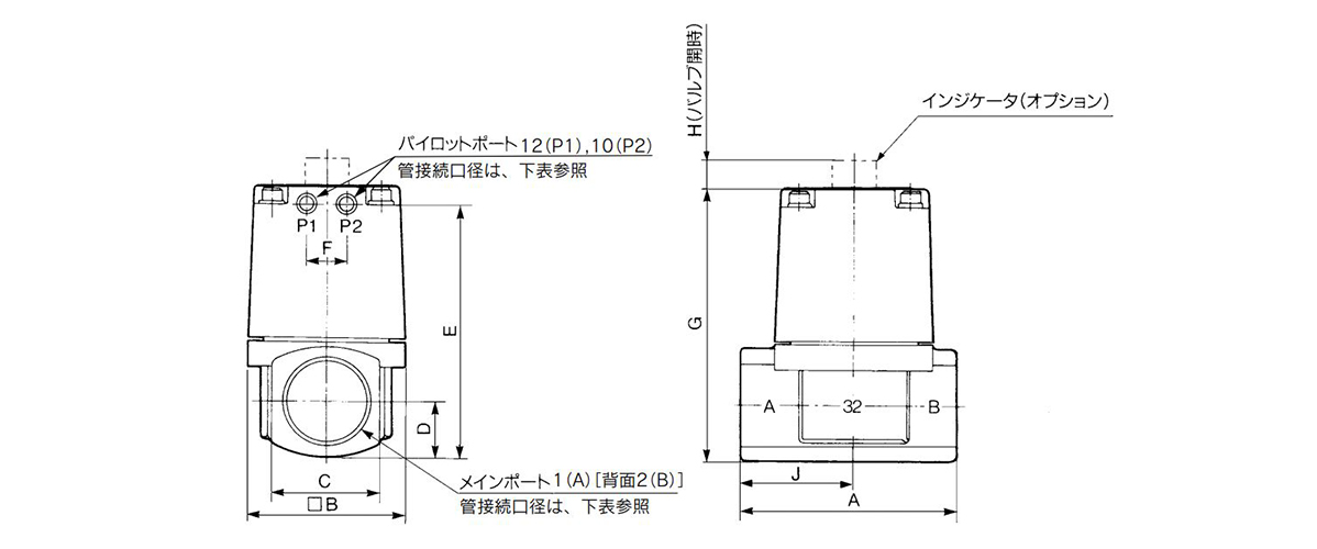
Piping connection port diameter: 32A, 40A, 50A dimensions and diagram
| Model | Main Port 1 (A), 2 (B) | Pilot Port 12 (P1), 10 (P2) | A | B | C | D | E | F | G | H | J |
|---|---|---|---|---|---|---|---|---|---|---|---|
| VND50□D-32A | 1 1/4 | 1/8 | 105 | 77 | 53 | 26.5 | 121.5 | 20 | 130.5 | 8 | 55 |
| VND60□D-40A | 1 1/2 | 1/4 | 120 | 96 | 60 | 30 | 138 | 24 | 148 | 10 | 63 |
| VND70□D-50A | 2 | 1/4 | 140 | 113 | 74 | 37 | 161 | 24 | 171 | 12 | 74 |
Piping Connection Port Diameter / Flange Type: 32F, 40F, 50F
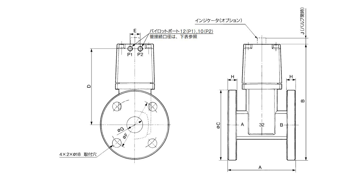
Piping connection port diameter / Flange type: 32F, 40F, 50F dimensions and diagram
| Model | Compatible Companion Flange 1 (A), 2 (B) | Pilot Port 12 (P1), 10 (P2) | A | B | C | D | E | F | G | H | J |
|---|---|---|---|---|---|---|---|---|---|---|---|
| VND50□D-32F | 32 | 1/8 | 130 | 211.5 | 135 | 135 | 20 | 100 | 36 | 12 | 8 |
| VND60□D-40F | 40 | 1/4 | 150 | 227 | 140 | 147 | 24 | 105 | 42 | 12 | 10 |
| VND70□D-50F | 50 | 1/4 | 180 | 251 | 155 | 163.5 | 24 | 120 | 54 | 14 | 12 |
Precautions
External Pilots
For the pilot port 12 (P1) and 10 (P2) piping, follow the information below for the relevant model.
- Port 12 (P1): VND□O□D external pilot / VND□O2D bleed port
- Port 10 (P2): VND□O□D bleed port / VND□O2D external pilot
SMC recommends installing a silencer on the bleed port to prevent debris from getting into the valve.
Piping
Use heat resistant parts for fittings, tubing, etc. (Compression fittings, fluorine resin tubes, copper piping, etc.)
Other Precautions
- *See the SMC catalog for information other than that detailed above.
- *Pictures are of representational models.
Adiabatic Space
There is a gap between the body and cover for heat insulation (*approx. 1 mm [see figure below]).
Detailed view of adiabatic space
Référence pièce
|
|---|
| VND500D-32F |
| VND500D-32F-L |
| VND502D-32F |
| VND502D-32F-L |
| VND600D-40F |
| VND600D-40F-L |
| VND602D-40F |
| VND700D-50F |
| VND700D-50F-L |
| VND702D-50F |
| VND702D-50F-L |
| Référence pièce |
Prix unitaire standard
| Quantité minimale de commande | Remise sur volume | Type à commutation | Type de connexion | Filetage nominal de tuyauterie | Type d'entraînement | Embase nominale de tube | Diam. d'orifice (Ø) | Plage de températures de fonctionnement (°C) | Option | Matériau du corps | |
|---|---|---|---|---|---|---|---|---|---|---|---|---|---|
471.32 € | 1 | 26 jours | Normalement fermés | Embase de tube | - | Type pilote | 32 | 32 | -5~ 60 | Aucun | Alliage de cuivre | ||
484.81 € | 1 | 26 jours | Normalement fermés | Embase de tube | - | Type pilote | 32 | 32 | -5~ 60 | Avec indicateur (vérification visuelle du fonctionnement) | Alliage de cuivre | ||
471.32 € | 1 | 26 jours | Normalement ouvert | Embase de tube | - | Type pilote | 32 | 32 | -5~ 60 | Aucun | Alliage de cuivre | ||
484.81 € | 1 | 26 jours | Normalement ouvert | Embase de tube | - | Type pilote | 32 | 32 | -5~ 60 | Avec indicateur (vérification visuelle du fonctionnement) | Alliage de cuivre | ||
567.84 € | 1 | 26 jours | Normalement fermés | Embase de tube | - | Type pilote | 40 | 40 | -5~ 60 | Aucun | Alliage de cuivre | ||
586.00 € | 1 | 26 jours | Normalement fermés | Embase de tube | - | Type pilote | 40 | 40 | -5~ 60 | Avec indicateur (vérification visuelle du fonctionnement) | Alliage de cuivre | ||
567.84 € | 1 | 26 jours | Normalement ouvert | Embase de tube | - | Type pilote | 40 | 40 | -5~ 60 | Aucun | Alliage de cuivre | ||
734.06 € | 1 | 26 jours | Normalement fermés | Embase de tube | - | Type pilote | 50 | 50 | -5~ 60 | Aucun | Alliage de cuivre | ||
753.56 € | 1 | 26 jours | Normalement fermés | Embase de tube | - | Type pilote | 50 | 50 | -5~ 60 | Avec indicateur (vérification visuelle du fonctionnement) | Alliage de cuivre | ||
734.06 € | 1 | 26 jours | Normalement ouvert | Embase de tube | - | Type pilote | 50 | 50 | -5~ 60 | Aucun | Alliage de cuivre | ||
753.40 € | 1 | 26 jours | Normalement ouvert | Embase de tube | - | Type pilote | 50 | 50 | -5~ 60 | Avec indicateur (vérification visuelle du fonctionnement) | Alliage de cuivre |
Loading...
Informations de base
| Type | Type à fonctionnement pneumatique | Fluide applicable | Vapeur | Environnement de fonctionnement | Standard |
|---|
Configurer
Propriétés de base
-
Type à commutation
- Normalement fermés
- Normalement ouvert
-
Filetage nominal de tuyauterie
-
Type d'entraînement
- Type pilote
-
Embase nominale de tube
-
Diam. d'orifice(Ø)
-
Option
- Aucun
- Avec indicateur (vérification visuelle du fonctionnement)
- Avec support
-
Matériau du corps
- Acier inoxydable
- Alliage de cuivre
-
Type
- VND10
- VND20
- VND30
- VND40
- VND50
- VND60
- VND70
-
Type de connexion
- Rc (R)
- G
- NPT
- NPTF
- Embase de tube
- Rc (R)
-
Filtrer par type de données CAO
- 2D
- 3D
Filtrer par jours d'expédition standard
-
- Tous les articles
- 4 jours ou moins
- 26 jours ou moins
- 33 jours ou moins
Propriétés optionnelles
- Les spécifications et les dimensions de certaines pièces peuvent ne pas être intégralement indiquées. Pour plus de détails, reportez-vous aux catalogues des fabricants .
Assistance technique
Mode de paiement


Fabrication à la demande
Certificats


Copyright © MISUMI Corporation All Rights Reserved.